Advanced Configuration
Information and references which are useful for integrators using Reactor to create advanced configurations in Config tab or JSON editor.
- Advanced Fader Range Setup
- Double click button
- External Camera Select
- Fader custom curve
- IO References
- Joystick Override / Hold Group guide
- Page Layers
- Pan/Tilt/Zoom Rocker Sensitivity and Curve Setup
- Presets Functions
- RCP Pro / RCPv2 :: Control more than 8 cameras
- Separating Zoom Sensitivity from Pan and Tilt Sensitivity
- Switching Projects via a Button in Reactor
- Switching Projects via external HTTP Request
- Understanding Flags
- Variables
- Virtual Triggers
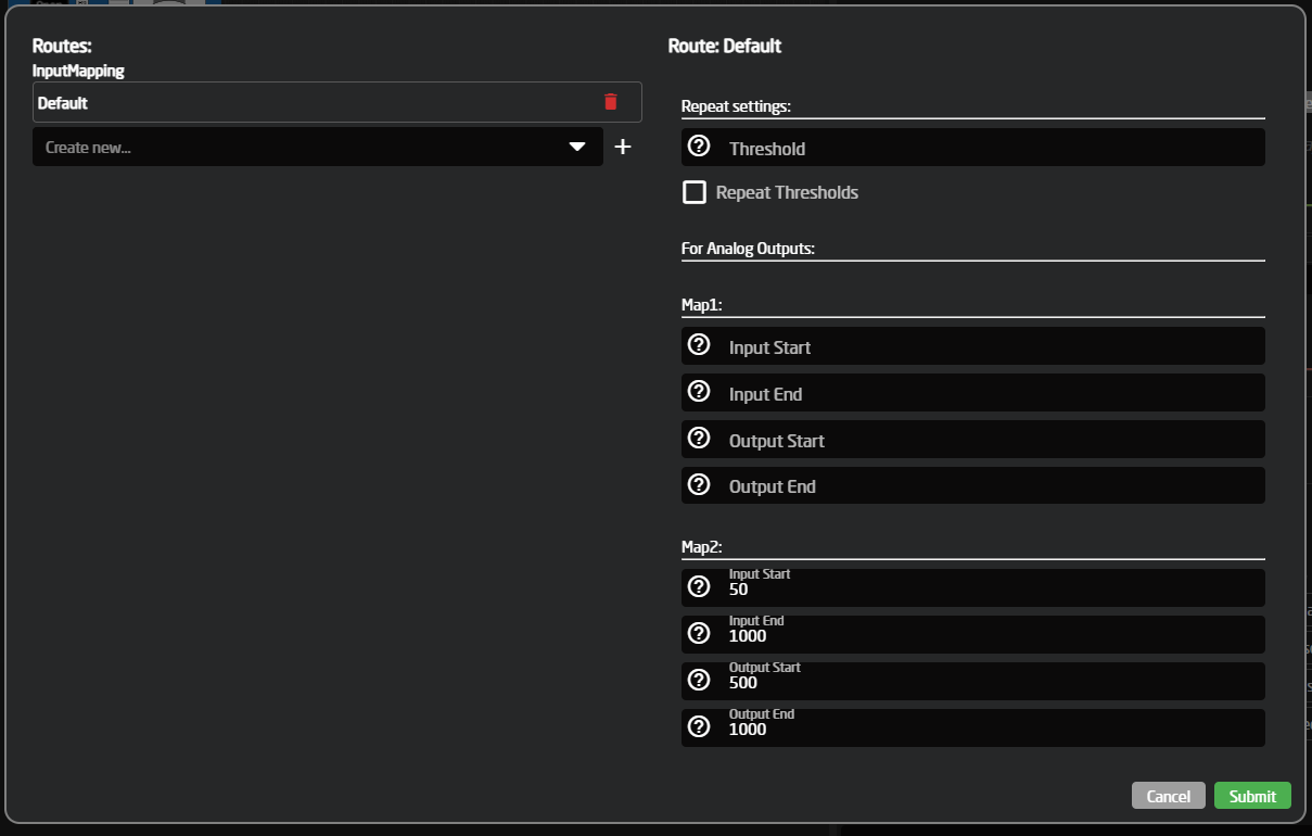
Advanced Fader Range Setup

"EventHandlers": {
"change": {
"EventPreProc": {
"A2A": {
"InputMapping": {
"Default": {
"Map1": {
"InputEnd": 1000,
"OutputStart": 500,
"OutputEnd": 1000
}
}
}
}
},
"BinarySetValues": {},
"IOReference": {}
}
},
"EventHandlers": {
"change": {
"EventPreProc": {
"A2A": {
"InputMapping": {
"Default": {
"Map1": {},
"Map2": {
"InputStart": 50,
"InputEnd": 1000,
"OutputStart": 500,
"OutputEnd": 1000
}
}
}
}
},
"BinarySetValues": {},
"IOReference": {}
}
},
Feedback
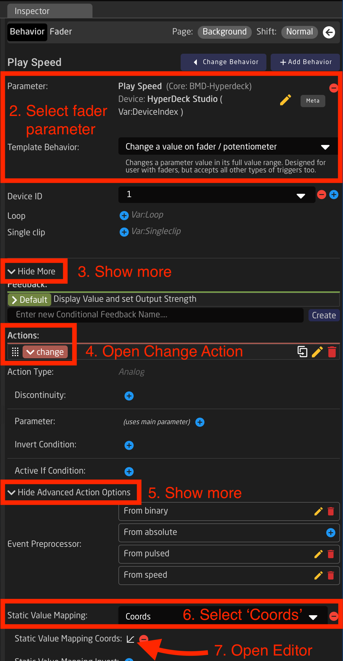
The above section only covers how to configure the eventhandler. For getting correct feedback for motorfaders, an additional step is needed.
Open the default feedback handler, and open the advanced feedback options. Select a Static Value Mapping Type of 'Coords'. Now add the Static Value Mapping Coords graph. Open the Coords popup and press '+' to add a new point. Set this new point to the same mapping as the eventhandler map. This might take some experimenting.
The Json should look something like this:
"FeedbackDefault": {
"Extended": {
"IOReference": {},
"StaticValueMapping": {
"Type": "Coords",
"CoordPairs": [
[
0,
0
],
[
900,
1000
],
[
1000,
1000
]
]
}
}
}Double click button
You may wish to detect 'double-click' or 'triple-click' on buttons. This would be useful for showing special menus (layers) - or sending commands that need a little more security.
To detect 'multiple-clicks' we use 'Event handler - preprocessor'.
In this simple guide we want to control a variable called "ShowMenu". It has just two options: off / on.
We create a behavior on a button - It must be double-clicked in order to set "ShowMenu" to 'on'
Create button behavior
Create Event handler
• click 'Show more' > locate Event handler section > enter name "DblPress" and click 'Create' > click new Event handler to open it
- Handler type: Binary
- Set values: 'on'
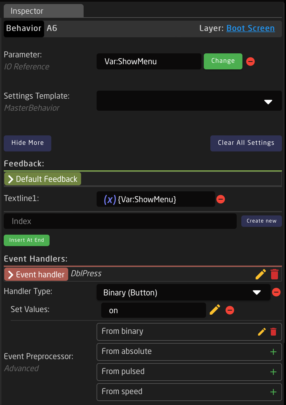
Create preprocessor (from binary)
• Locate the Event Preprocessor section > next to From binary > click '+' to create > click it to edit
• select 'Default' > click '+' to create > click 'ActDown' to open settings
- Repeat: Delayed <-- start a timer
- Repeat delay: 300 <-- timer lenght in milleseconds
- Burst count: 2 <-- number of required button presses to proceed with output trigger
- Output trigger: ActDown
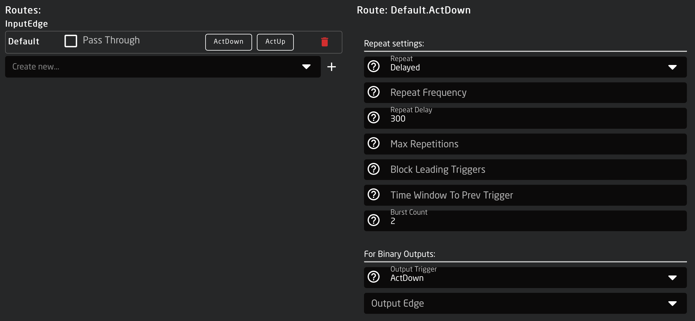
With the above, you must press button 2 times within 300ms for the action to proceed (ie. set ShowMenu to 'on')
External Camera Select
With a few simple steps it is easy to set up an external camera selector on your Standard or Pro Class Skaarhoj PTZ panels. This can be used to have the camera select of your PTZ panel follow along with a video router or video switcher or it could be used to set up an additional Skaarhoj panel for an expanded camera select.
External Camera Select from External Device
- Make sure you have connected to all your needed devices on the Home Page
- On the Home Page, open the Camera Selector settings table.

- Enable Show Advanced in the Camera Selector

- Input a unique number to associate with the camera in the Ext. Cam Number column.
It is recommended to use the same number as is used for the input on the triggering device. Example if using a BMD VideoHub and the camera is Input 5, set the Ext. Cam Number to 5 as well.

-
Navigate to the Configuration Page.
- If setting up for a single panel only, click anywhere on the panel background (blue part) to open the Inspector on the configuration base layer.

- If setting up for multiple panels within the same project, open the Configuration Tree and click on the Root Layer at the bottom.


- Create Variable called ExternalCameraSelect Exact name is needed as it is prebuilt into a Virtual Trigger.

- Adjust the needed range of the Variable based on numbers used in the Camera Selector on the Home Page for the Ext. Cam Number. The range used should encompass all numbers you have defined. By default the range is 1-10, if that is all that is needed, then no adjustment is required.

- Create a Virtual Trigger to set the ExternalCameraSelect Variable based on desired parameter. Name the Virtual Trigger something that will allow you to easily identify what it is doing.
Shown is an example using a Blackmagic VideoHub, but it can be any other device.

- Open the newly created Virtual Trigger.
-
Set the Mode to Change.

- For the IF parameter, set the source of the trigger. In this instance a route of the VideoHub on a specific output will be used to change the ExternalCameraSelect variable.


- For the THEN parameter, select the ExternalCameraSelect Variable


- The needed Template Behavior for the THEN should be auto suggested. If it is not, you will want to select SET SPECIFIC VALUE.

- For the Value, set again the same parameter you used for the IF parameter. In this example it was Output 1 of a Blackmagic VideoHub.
This is why it is recommended to set the Ex. Cam Number in the Camera Selector Settings Table to match the Input number from the trigger source. It can then easily be synced.

- The trigger is now set up and can be used. Note that any change in the source trigger's status will trigger the route (within the variable range set) but you are able to freely choose a different camera to control from the camera select row without it retriggering.
External Camera Select from External TCP Command
- Add an instance of TCP Server as a device on the Home Page.

- On the Home Page, open the Camera Selector settings table.

- Enable Show Advanced in the Camera Selector

- Input a unique number to associate with the camera in the Ext. Cam Number column.

- Navigate to the Configuration Page.
- Click on the background of the panel in the controller section to open the background layer of the configuration in the Inspector.

- Create Variable called ExternalCameraSelect Exact name is needed as it is prebuilt into a Virtual Trigger.

- Adjust the needed range of the Variable based on numbers used in the Camera Selector on the Home Page for the Ext. Cam Number. The range used should encompass all numbers you have defined. By default the range is 1-10, if that is all that is needed, then no adjustment is required.
- Create a Virtual Trigger to set the ExternalCameraSelect Variable based on external trigger. Name the Virtual Trigger something that will allow you to easily identify what it is doing.

- Open the newly created Virtual Trigger.
-
Set the Mode to Change.

- For the IF parameter, set the source of the trigger. In this instance a specific TCP command will be used to change the ExternalCameraSelect variable.

Device Core: TCP Server
Parameter Name: Integer Value
Number: Literal: 1

- For the THEN parameter, select the ExternalCameraSelect Variable
First Expand System to select Change Variable behavior

Second click to edit the parameter
Third select the ExternalCameraSelectVariable
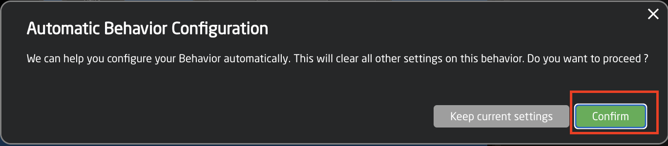
Fourth select Confirm when prompted.
- The needed Template Behavior for the THEN should be auto suggested. If it is not, you will want to select SET SPECIFIC VALUE.

- For the Value, set again the same parameter you used for the IF parameter.

- The trigger is now set up and can be used by sending the command Int#1=X (X = the number set in Ex. Cam Number column in the Camera Select Settings Table on the Home Page) to the IP address of the Blue Pill device and the port defined in the TCP Server device details on the home page.

Example using a Terminal window on Mac.
External Camera Select from Skaarhoj Panel in the Same Project
- Make sure you have connected to all your needed devices on the Home Page
- On the Home Page, open the Camera Selector settings table.
- Enable Show Advanced in the Camera Selector
- Input a unique number to associate with the camera in the Ext. Cam Number column.
- Repeat the process for your second panel.
The camera select doesn't need to be in the same order, but the same number needs to be associated with each camera.
- Navigate to the Configuration Page.
- Open the Configuration Tree and click on the Root Layer at the bottom.
- Create Variable called ExternalCameraSelect Exact name is needed as it is prebuilt into a Virtual Trigger.
- Adjust the needed range of the Variable based on numbers used in the Camera Selector on the Home Page for the Ext. Cam Number. The range used should encompass all numbers you have defined. By default the range is 1-10, if that is all that is needed, then no adjustment is required.
- Close the Configuration Tree but remain on the configuration page.
- Click on any of the camera select buttons for the panel you want to trigger the external camera select from. This will open the details in the Inspector.

- In the Inspector, click on the first Show More to expand it.

- Create another Action called externalselect

- Set up the action as follows:
 Action Type: Binary (Button)
Type (Press/Release): ActUp
Values to Set: Behavior:Const:ExtCamSelect
 Parameter: Var:ExternalCameraSelect
- If you would like to trigger the external camera select to go both ways, repeat steps 11-14 for additional panels.
Fader custom curve
What is a fader curve
Fader movement from bottom to top has a range from 0-1000, and by default this is a straight line - or linear. But sometimes you want the fader to have more details - or 'throw' - in certain areas, on the cost of less details in other areas. This can be described with points on the line that bends it in different ways - we call this a fader curve.
See these examples:
|
Linear (default) |
Details in top |
Details in middle |
No top/bottom |
More points = smooth |


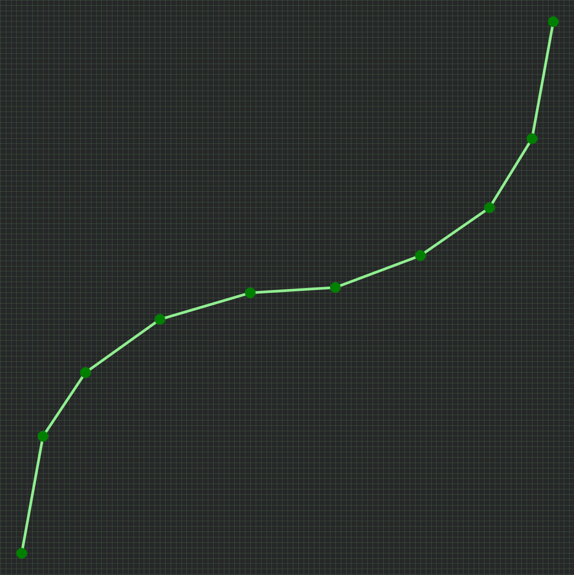
This means: The more vertical the line is, the faster it moves past an area (less detailed). And opposite: The more horisontal the line is, the longer it stays in the same area (more detailed).
So, if you have an audio channel and want more fader accuracy in the loud end, you'd make a curve similar to example 2; 'Details in top'.
Access the curve editor
Reactor has a built-in graphic curve editor. It allows you to create any custom fader curve you want, including the examples above. You access it on the Configuration page by selecting a fader hardware component, and open the advanced settings within the Inpector. The curve editor is, of course, only available when selecting a 'fader' component, and not on buttons or knobs.
|
Guide to open the curve editor:
|
|
Edit curve
|
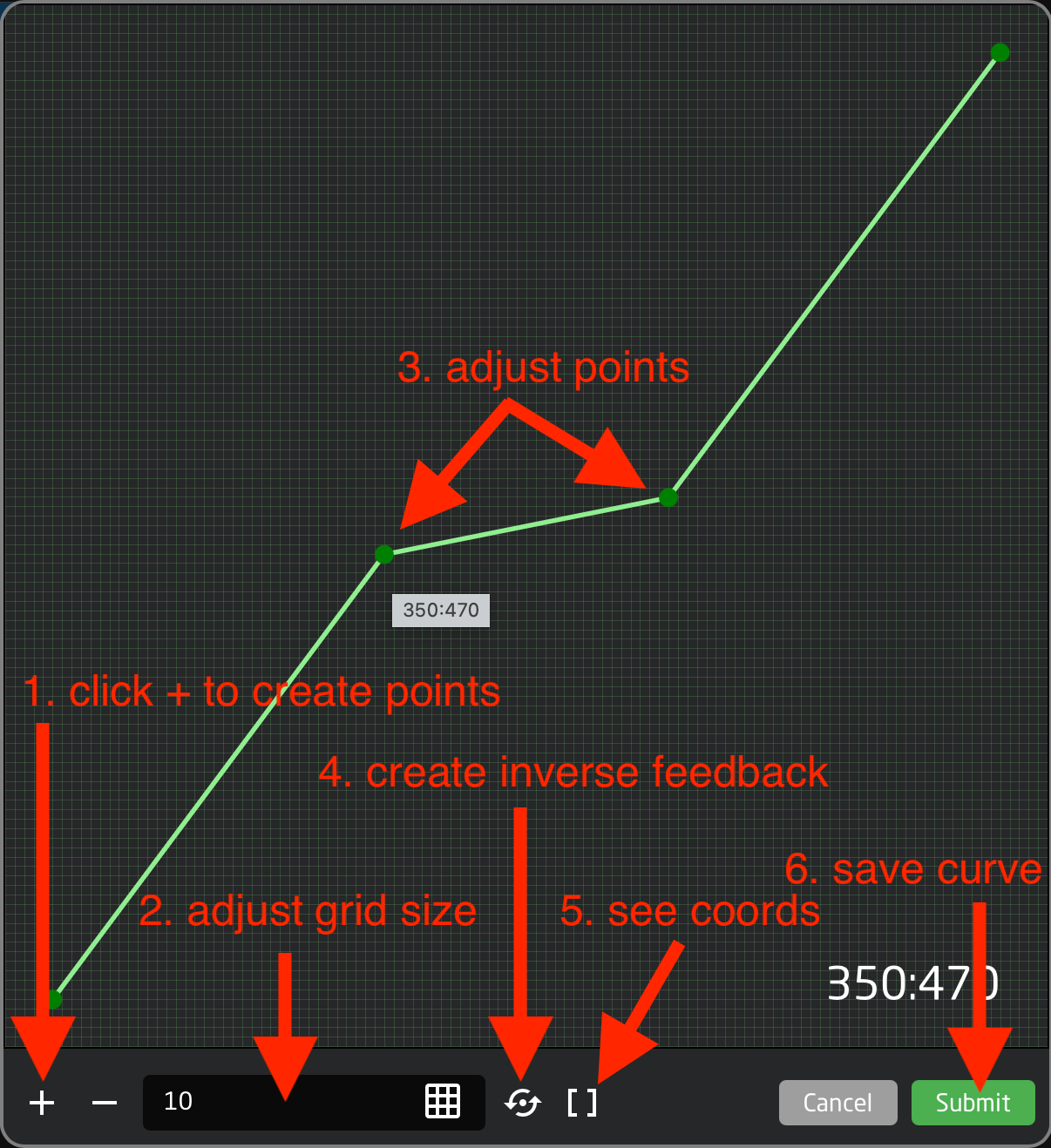
In the curve editor you add points, and drag them in the 0-1000 grid (0,0 being bottom and 1000,1000 being top).
Here's a guide to the features:
|
|
Inverted feedback
Please know that often a SKAARHOJ panel sends values to a device - and then it listens for return-values from the device. So, you may move the motor-fader, but the fader position is actually updated by the return-value from the device.
In this case, having a custom curve on the data you send (the Action) - also makes it necessary to have an inverted version of the same curve on the data you listen for (the Feedback). This will prevent the fader from 'jumping' in strange ways.
As mentioned above (in line 5), you simply click the 'circle-arrow' icon to automatically create a feedback with an inverted curve. And do remember to click it again to update it, if you have edited the curve.
IO References
This documentation has moved, see here: https://docs.skaarhoj.com/3_configuration/ioreference.html
Joystick Override / Hold Group guide
This is a guide on how to handle 'Joystick override' and 'Hold groups' for CCU operators - allowing automatic routing of cameras to a confidence monitor.
Imagine these operator steps:
- CCU 1 presses the joystick :: Route cam 1 to monitor
- CCU 4 presses the joystick :: Route cam 4 to monitor
- CCU 2 presses the joystick :: Route cam 2 to monitor
... - CCU 4 lets go of the joystick :: (nothing happens)
- CCU 2 lets go of the joystick :: Return to route cam 1 to monitor
- CCU 1 lets go of the joystick :: Return to original input for monitor
You can of course have more CCU's - and the order of who does what when is remembered by the system.
Prerequisite
This setup requires a 4 things:
- Blue Pill device --> Is the brain, running the config and controlling both ETH-GPI Link and video switcher/router
For example 'Blue Pill Server' : https://www.skaarhoj.com/product/blue-pill-server - ETH-GPI Link --> Handles the GP inputs from the CCU's
https://www.skaarhoj.com/product/eth-gpi-link - A number of CCU's with GP output for joystick press
- A video switcher/router (for example; Aja Kumo, ATEM, Tricaster, vMix etc.)
NOTE: The Blue Pill device must have Reactor 2.2.3-pre10 or later installed. This is handled on the 'Packages' page.
NOTE: The ETH-GPI Link must be in 'Blue Pill Mode', which means it's controlled by a Blue Pill device.
Configuration
- Goto IP address of Blue Pill device to see Reactor, the configuration manager.
- Click 'Add panel' and select your ETH-GPI Link
- Click 'Add device' and select your routing device
- In the ETH-GPI Link configuration drop-down menu, select default configuration 'Tally & Routing'
- Click 'Camera Selector' to open settings -> Add empty rows (by holding Shift) -> Set route index [1, 2, 3..]
(these are the camera inputs on the switcher/router) - Click 'Routing Trigger' to open settings -> Select the output to route to
- Click 'GPIO Input mapping' to open settings -> Change type from ‘Tally Program’ to ‘Route Index’
- Click 'Config Variables' to open settings -> Select 'Press' or ‘Hold down’
Advanced step to share stack between multiple [Blue Pill Inside] RCP panels in the same configuration:
- Goto Configuration page -> click '>>' in window left/top top show Layer Tree
- Find variable: HoldGroupState -> right-click it and copy it
- Scroll down to lowest Root layer -> right-click it and paste variable here (variables here are shared by all panels)
Screenshots
Same as config steps above
2: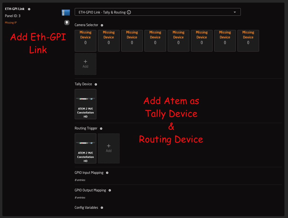
5:
6:
7:
8:
Page Layers
Please note: This video is made for Reactor 1.x
We have since released Reactor 2.x - and the video is no longer up-to-date.
This guide show you how to make Page Layers.
Say you wish control 8 parameters on a camera, but only have 4 encoders on your controller. In this case you make two 'Pages' - or layers - and assign different commands in each 'Page'. You then assign a button to toggle between the pages.
Pan/Tilt/Zoom Rocker Sensitivity and Curve Setup
For all our default PTZ configs we have pre-defined up to 4 variables for you to use to tune the feeling of the joystick and zoom rocker to fit the feeling between multiple cameras to your liking.
Before in time, you would find one param that would control all 3 axes on the joystick (L/R, U/D & Rotate) as well as the Zoom rocker. This has now been split out by default to these for options that can be set pr. camera and that will remember their values between reboots, so you don't have to remember them.
The for new params are:
- PT_Speed -> Controls the scale on U/D, L/R Joystick movements (Max Speed)
- PT_Curve -> Controls the curve for U/D, L/R Joystick movements (Expo)
- Z_Speed -> Controls the scale of the Zoom rocker and Joystick rotation (Max Speed)
- Z_Curve -> Controls the curve of the Zoom rocker and Joystick rotation (Expo)
The two-speed variables are direct replacements for the old JoystickSens variable and they go just like the old variable from 1-10, with the default being 10. This correlates to a min setting of 10% of the max speed and up to the full 100% speed.
So in short 1 = 10%, 2 = 20%, 5 = 50% and 10 = 100% speed on a fully deflected joystick/rocker.
Then we have the Two new curve variables that actually replace the old JoystickExpo variable. The chances of you having seen that variable in Reactor are very slim as it's not been part of the configs before, even though it has been set as an option in all configs.
The new PT_Curve and Z_Curve replace this old variable with a name that makes more sense as well. What we control here is the amount of Expo we want on the joystick. These variables go from 0-25 giving us a wide selection from 0 = linear to 25 = 75% expo. The reason we have limited it by default to a max of 75% is that otherwise it gets so sharp that it's basically just an on/off behaviour. Adjusting this variable will give you more resolution in the middle of the joystick without losing max speed at the ends. combine this with the speed above to get the best feeling for you.
In order to visualise what the curve variables do, please take a look at this image, if you have the curve set to 0 then your joystick will follow the green curve, then as you move up towards 25 you will get closer and closer to the red curve. Thus giving you more resolution in the middle.
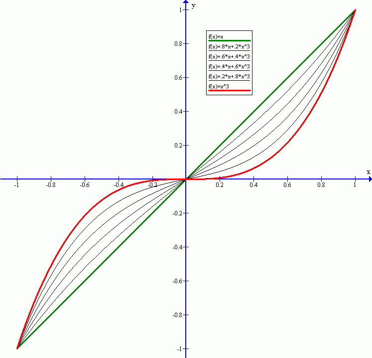
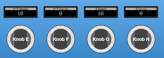
Image showing these four variables mapped to the encoders in a config:
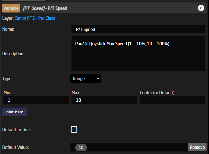
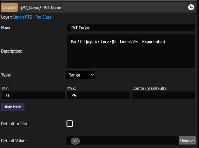
Example of the P/T Speed and P/T Curve variable setup (Note that they also have "Persistent" = true):
Here is the full definition of the 4 variables in their full JSON setup:
This snippet is taken from the file: SKAARHOJ.Devices.Canon-XC.ProClass.Basic
"PT_Curve": {
"Name": "P/T Curve",
"Description": "Pan/Tilt Joystick Curve (0 = Linear, 25 = Exponential)",
"MinMaxCenterValue": [
0,
25
],
"Default": [
"0"
],
"Persistent": true
},
"PT_Speed": {
"Name": "P/T Speed",
"Description": "Pan/Tilt Joystick Max Speed (1 = 10%, 10 = 100%)",
"MinMaxCenterValue": [
1,
10
],
"Default": [
"10"
],
"Persistent": true
},
"Z_Curve": {
"Name": "Z Curve",
"Description": "Zoom Rocker Curve (0 = Linear, 25 = Exponential)",
"MinMaxCenterValue": [
0,
25
],
"Default": [
"0"
],
"Persistent": true
},
"Z_Speed": {
"Name": "Z Speed",
"Description": "Zoom Rocker Max Speed (1 = 10%, 10 = 100%)",
"MinMaxCenterValue": [
1,
10
],
"Default": [
"10"
],
"Persistent": true
}
One thing you will notice when you go to look at a PTZ behaviour is that you cant find where these variables are actually used, as for the moment this is not visible in the UI, so, for now, you will have to add or change this via the JSON editor.
If we go take a look at where this would become visible at some point in the future, then that would be here inside the blue box, inside a part called "ValueMapping":
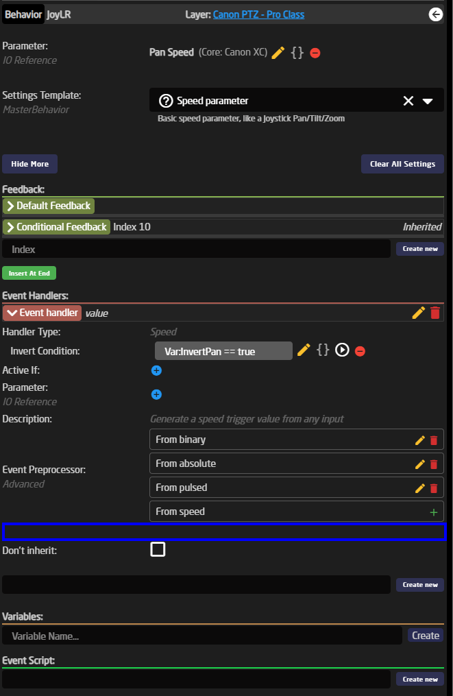
If we then Click the "Show JSON" button then, we will see the full config for the Pan joystick setup for Canon XC:
{
"ParentID": "SKAARHOJ:SpeedControl",
"Name": "Pan",
"EventHandlers": {
"value": {
"ValueMapping": {
"ScalingDivisor": 10,
"ScalingIOReference": {
"Raw": "Var:PT_Speed"
},
"ExpoDivisor": 30,
"ExpoIOReference": {
"Raw": "Var:PT_Curve"
}
},
"InvertCondition": "Var:InvertPan == true"
}
},
"IOReference": {
"Raw": "DC:canon-xc/Var:DeviceIndex/panSpeed"
}
}What we look for is again the "ValueMapping" field where we can see a ScallingDivisor so that's how we get the 10% steps on the PT_Speed variable 100%/10 = 10% step size
Then the same for the Curve, we have an ExpoDivisor that is set to 30 so 100%/30 = 3% expo pr step and by having our PT_Curve variable limited to only 25 limits the max setting on the controller to 25 * 3% = 75% expo. Thus preventing the curve from becoming unusably sharp.
Don't hesitate to play around with these options to get the tunning fully right to your liking.
Presets Functions
Presets
- Generally speaking, presets store and recall parameter values and triggers in Reactor
- The values to be stored can be predefined in a preset profile or they can be completely arbitrary (recording what changes)
- A preset profile can define values across device cores, device IDs and parameter dimensions - or they can be narrowed down
- With narrow preset profiles, there are inherent opportunities to use presets to copy/paste sets of values between devices and dimensions
- Reactor supports an infinite amount of preset profiles (re-)defined anywhere in the layer tree
- Storage and recall of a preset can work either instantaneously or played back over time
- When recorded and played back over time, values are organized in multiple segments. Each segment is essentially a time line and at the end of a timeline, playback will continue to the next segment either automatically or by user invocation (waiting for user input).
- Playback order of segments can be shuffled and waiting time between segments can be randomized. Playback for a timeline can be looped
- Recording and playback allows cancellation which will restore the state before recording or playback.
- Support for ganged recording and playback of multiple preset numbers, device ids, and dimensions (fairly exotic, honestly)
- Prepared for parameter animation (must be implemented in devicecollection)
Commands:
NextSegment (trigger)
During recording, this will end the segment and start a new one assuming there has been values added.
During playback, this will skip to next segment
AddUserWait (trigger)
Like NextSegment, but when used during recording it will insert a User Wait at the end and cap the segment length to the last added value.
Play (trigger)
Starts playback
PlayToggle (trigger)
Starts or stops playback
PlayToggleNext (trigger)
Starts or stops playback, except if waiting in which case it will
PlaySkip (trigger)
Starts playback, and skips to next segment if already playing (which may result in stopping altogether)
PlayPause
Starts playback and toggles pause if already playing
PlayPauseNext
Starts playback and toggles pause if already playing, unless at a user wait in which case it skips to next.
Record (trigger)
Starts recording
RecordToggle (trigger)
Starts or stops recording
RecordNewSegment (trigger)
Starts recording, and creates new segment on second press
RecordAddUserWait (trigger)
Starts recording, and creates new segment with user wait on second press
Stop (trigger)
Stops recording or playing
Delete (trigger)
Deletes preset if it is not recording or playing
Cancel (trigger)
If recording, it will stop recording, recall the values from before recording and reinstate the previous content for the preset
If playing, it will stop playing and recall the values from before playing.
Recall (trigger)
Instantly recalls the final values of the first segment of a preset.
RecallStateFromBeforeRecording (trigger)
Recalls the initially stored state of a given preset
DurationRandomExtension (Integer value, ms)
Sets the Random extension value for a given recorded preset.
Loop (bool)
Enable looping for a preset
Shuffle (bool)
Enable shuffle for a preset
RCP Pro / RCPv2 :: Control more than 8 cameras
Optimal control
For optimal control we suggest having a separate RCP panel for each camera.
This is how camera control was intended, when Sony invented the RCP form factor in the beginning of time.
Default 'Camera Control' configuration
RCP Pro and RPCv2 panels have a feature rich pre-made default configuration called 'Camera Control'.
It is selected on Home page in the configuration drop-down menu, right next to the panel icon.
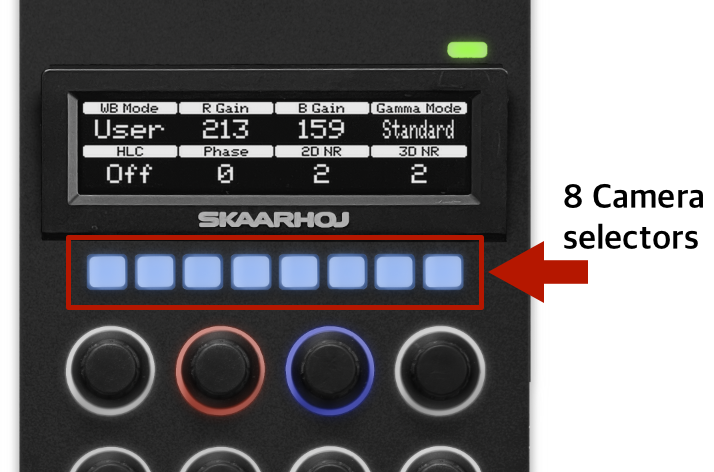
This configuration allow you to add up to 8 cameras, even from different brands.
And the 8 small buttons in the panel top are a perfect fit to use for 'Camera Select 1-8'.
Options for more cameras
If you need to control more cameras you can..
- purchase more RCP panels
- create your own custom configuration from scratch
- modify the 'Camera Control' configuration to handle more cameras
How to modify the 'Camera Control' configuration
This includes:
- increasing the allowed number of cameras on Home page
- create a variable to store 'current camera selector page'
- assign the variable to the Generator for camera select (to automatically create more pages)
- assign the variable to a button (to toggle pages)
You can watch a screen recording video (2min 24sec), that shows you how to modify the configuration step-by-step.
Download the video here:
https://drive.google.com/file/d/1GC_ap9sWij_W8nkptEJa7tfiHDLgNYlp/view?usp=drive_link
And here's a written guide on how to do it:
Add cameras
• Home page
• in window right, click ‘Add device’ -> add all cameras
• in window center, select ‘Camera Control’ in the configuration menu
• click ‘+ icon’ -> click ‘Add all supported devices’
Expand max number of cameras to more than 8 before the ‘+’ button disappears
• goto Configuration page
• click ‘>>’ icon to show Object Tree
• in very bottom/right of page, click ‘cogwheel’ icon to open Settings -> enable ‘Show IncludeLayers’
• now you see the layer ‘Default RCP PRO Configurattion’ -> click 'CameraSelector' to show it in Inspector
• scroll down, click ‘Show more’ -> edit ‘Max items’ from 8 to 16 (or how many you need)
• goto Home page -> add more cameras
Make sure the 8 buttons in panel top are used for ‘camera select’ - and not for ‘presets’
• goto Simulator page / or press buttons on actual panel
• press two buttons to open Engineering menu -> set Cam-row to ‘Cameras’
Create new variable to store ‘Selected page’
• goto Configuration page
• click panel background to see variables -> create new ‘CamSelectPage’ variable -> click it to open it -> set range max 2
Use variable in generator for 'Cam selectors' to automatically build more pages
• in Object Tree, open layer RCP > Camera Control > Normal Operation -> Cam 1-8
• click any of the 8 Cam buttons to select the generator in Inspector -> set ‘Paging Variable’ to the new ‘CamSelectPage’
Assign variable to button, to use for page-select
• click ‘<<‘ icon to hide Object tree
• click an available button, fx. X4
• select System > Change Variable > select the new CamSelectPage -> click Submit + confirm
Done.! The 8 camera select buttons in panel top now has 2 pages, and use button X4 to toggle between them.
Separating Zoom Sensitivity from Pan and Tilt Sensitivity
This page has been made obsolete in newer versions of Reactor.
By default Pan, Tilt, and Zoom are all controlled by the setting Joystick Sensitivity. This is not ideal for some users who would like Zoom to be controllable at its own sensitivity. To separate this out it is necessary to dive into the configuration and the json editor, but don't worry, it isn't too difficult.
This example will be done on the PTZ Extreme but can be applied to all configurations.
Joystick sensitivity is not set for the whole controller, but per camera configuration based on device core. The configuration in this instance is different from the panel mapping. There will be a different configuration added for each device core used.
Different brands might use the same device core, example: BirdDog, NewTek, Marshall all use the Visca device core.
This example was made on a Blue Pill running the following version:
SkaarOS v1.0
Reactor v1.0.5-pre11
System Manager v1.0.1-pre1
Hardware Manager v1.0.2-pre3
Using earlier versions can affect the look of the interface causing it to appear different. We recommend using at least the indicated versions or newer.
1. Determine the number of PTZ configuration in your set up.
In the set up example there are 3 different device cores used as indicated in the Devices section. All devices will be grouped by the used core in this section. 

3. Open the Tree to navigate to the Device Core Configurations. The tree expands from the bottom up, like a tree starting at the roots. (This is shown in a collapsed view)


5. Open the Tree Layer with the Joystick Sensitivity Variable. When selected the layer will change color and you will see it open in the Inspector on the right side of the screen.

6. Create a new variable called ZoomSens. This could be named anything, but it is best to use something that will be easy to remember and type later.

7. Open the ZoomSens variable to edit the details. Use the same details as the JoystickSens variable.
The name is however you would like it to display on the controller.
The type is Range
The Min is 1
The Max is 10 (The scale should not exceed 10)
Default value is 10

8. Go back to the Tree and select the JoyRot box in the same layer you are working in. This will open the joystick rotation (zoom) in the inspector.

9. DON'T PANIC
10. Open Show JSON for the JoyROT component.

11. Select Format

12. Select Show Parent Behavior

13. In the Window the pops up, select Format again. This will expand the data to see the whole JSON text.

14. Scroll down to the Joystick Sensitivity commands and copy the whole command set as seen below, every part is essential:

15. Close this window.
16. In the Inspector, find the BehaviorSetValues text in the JSON editor. Click after the comma and hit enter.

17. Paste in the text you copied from the Parent Behavior pop up.

18. Find the text in the pasted in command that say: "Var:JoystickSens"

19. Edit this text to say: "Var:ZoomSens" then press Save
If you did not name the variable you created earlier ZoomSens, you will type the name you did create here after the :

20. If there is a Zoom Rocker, you will need to do steps 18 + 19 for that hardware component as well.

21. The variable and command have now both been set up. The last step is to assign control of the variable to an encoder.
22. Go back to the tree view and navigate deeper in that device core configuration to the Camera Adjustment layer and open it. This will open the tree to see the different page layers of settings for the camera. They should be named based on the what they contain. 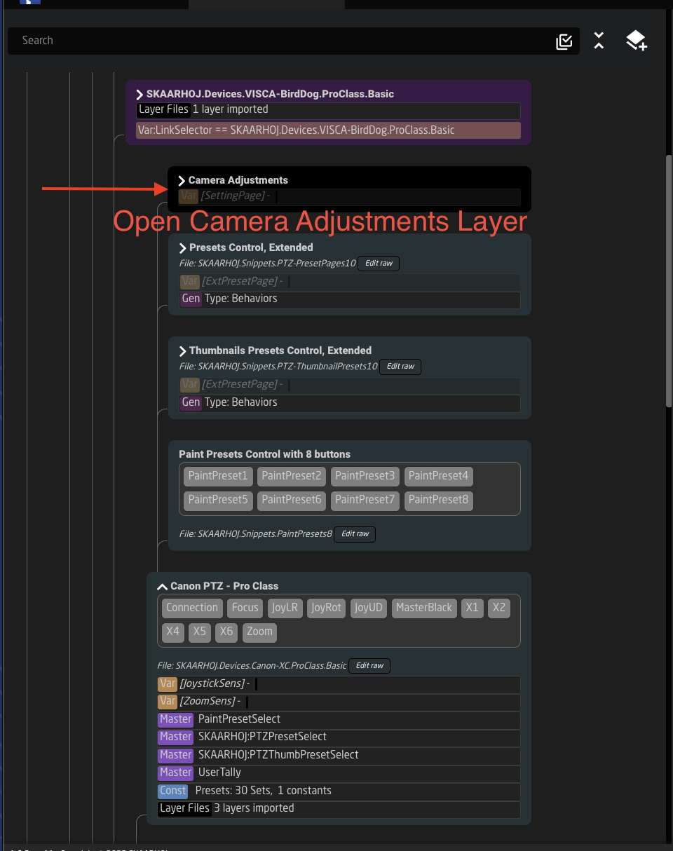

24. Find one of the encoders that does not currently have something assigned to it, you can see this by going to that page on your physical panel and seeing where a good place to put the Zoom Sensitivity Control would be. In this example I am using Encoder 4 (from right to left on the physical panel).
25. In the Inspector select Edit next to the Parameter.

26. In the pop up window, select Variable.

27. In the drop down next to Variable Name, select ZoomSens and press Submit.
28. After submitting the Behavior should either suggest or auto-assign Step Change. This is the correct behavior.

29. You should now be able to control Zoom Sensitivity separately from Pan and Tilt.

30. If you are combining cameras that use multiple device cores on your panel, you will need to go in and do the same in each device core configuration. In the example below there are 3 different configurations and we made the changes to the Canon configuration.

Switching Projects via a Button in Reactor
Reactor allows to switch the current project easily using a button.
Please Note, changing the current project will disconnect controllers if they are not configured in the project that is being switched to.
Make sure to configure the projects to be switched between in each project.
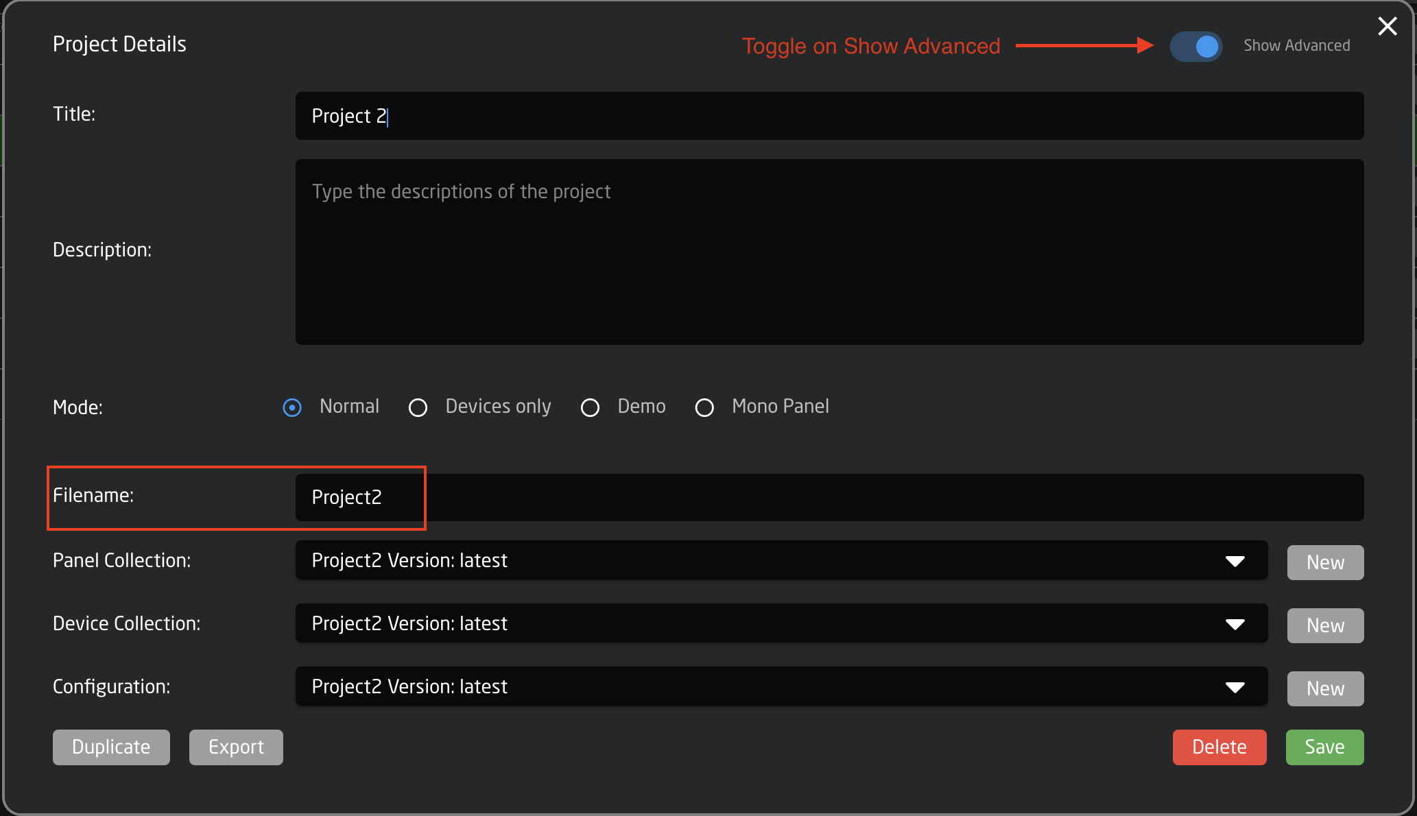
In the Project Manager, open the project details for the project you want to switch to. Copy the project's Filename exactly. It is necessary to toggle on Show Advanced to see the file name.
On the Configuration Page, select the button to configure. In the Inspector, select Switch Project under the System options.
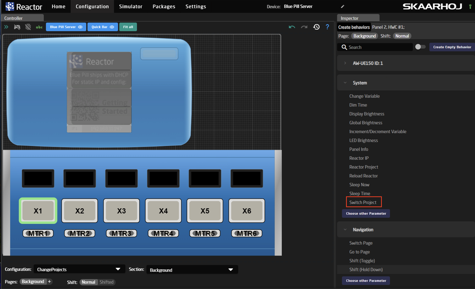
In the Inspector box, the parameter should open with a preselected selected Settings Template.

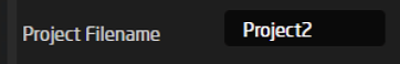
Fill in the Project Filename that was copied from the Project Manager into the Value field next to Project Filename. It is important that the file name is copied exactly as found in the Project Manager.
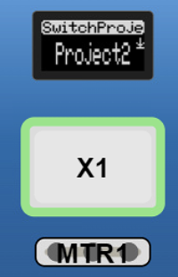
The project name should now appear on the display above the button (if the button does have an associated display).
Please Note, the switch is activated by a 1 second hold down of the button.
Another way to do it without the 1 second hold down.
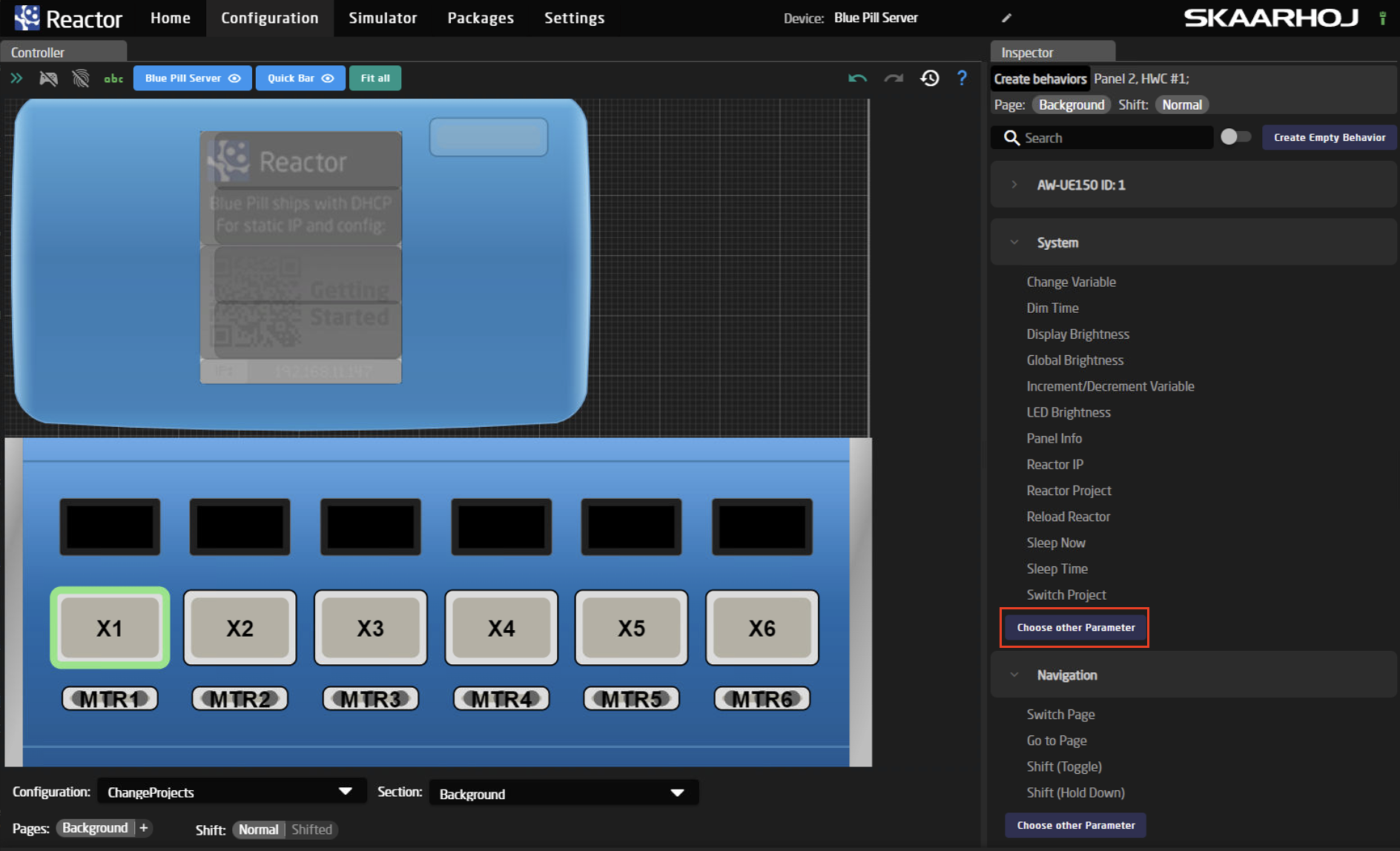
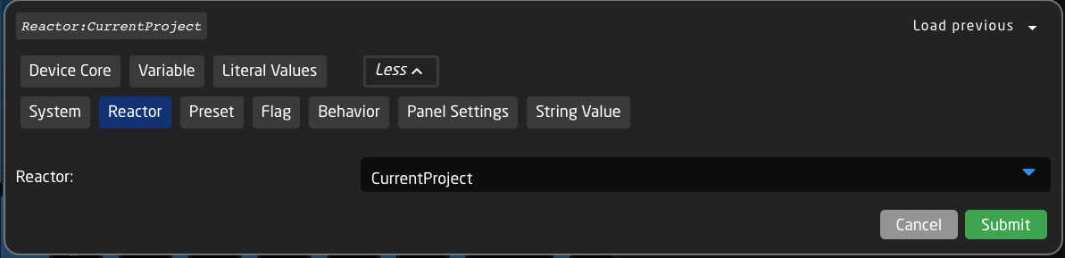
On the Configuration Page, select the button to configure. In the Inspector, select Choose Other Parameter under the System option.
In the dialog box that pops up select: Reactor/CurrentProject then Submit
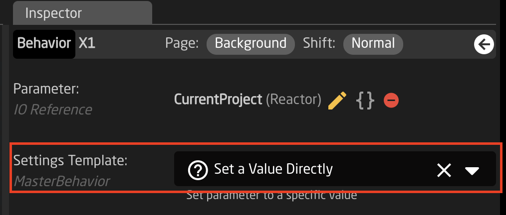
Returning to the Inspector, select Show More if you do not see Settings Template available.

In the Settings Template, select Set Value Directly:
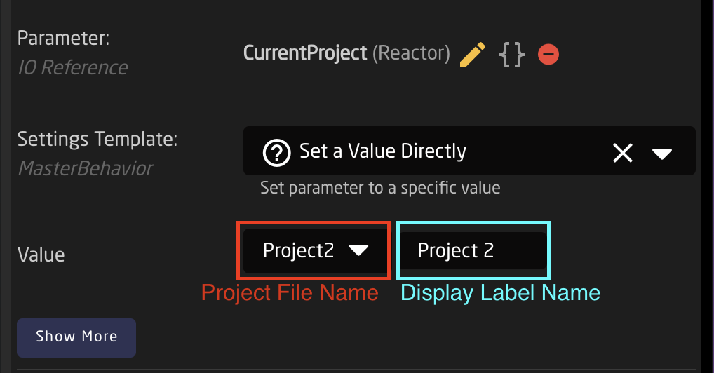
This should then give you the option to define the value needed.
The first box will contain the Project File Name as directly copied from the Project Details. The second box can contain any name you would like to be displayed on the hardware panel.
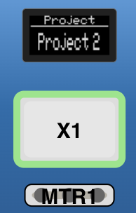
You should end up with a button like this:
Switching Projects via external HTTP Request
Reactor allows to switch the current project via an external HTTP POST request.
The endpoint used is: /reactorapi/selectproject
This request allows to use the skaarOS authentication via HTTP Basic Authentication (Use the latest version of system-manager to allow this (v1.0.1-pre1 and higher))
Curl example:
curl --location --request POST '192.168.0.20/reactorapi/selectproject' \
--header 'Authorization: Basic YWRtaW46c2thYXJob2o=' \
--header 'Content-Type: application/json' \
--data-raw '{"Filename":"MyProject"}'
Understanding Flags
This documentation might be outdated. Please consult the Reactor manual at https://docs.skaarhoj.com/11_advanced_topics/flag-groups.html
Inside reactor we have support for setting flags true or false. These flags are based around how TSL works to some extent and provides a list of true/false states with 4 "bits" per index.
Flags in reactor consists of 4 bits per index, that can be set true or false individually, each of these flag bits can be used for different things but you will mainly see them used for providing tally and routing support in configs as they are a great way to store the intermediate state that comes in from a GPI pin or from a device like an ATEM switcher. Then use the stored state to send the Tally to the cameras
The 4 "colors/bits" main use cases in the default configs for each color are:
|
Red |
Mainly used for Program Tally |
| Green | Mainly used for Preview Tally |
| Blue | Not widely used in default configs yet |
| White | Mainly used for storing what camera to Route on a mixer/videohub |
These are not limited to this use case, but this is the current convention we use internally.
Define flag groups and sync them up
When you use flags you will need to add them to your project as "Flaggroups" with a name and an Index.
One Important note is that ANY config that you have loaded in the project that uses the same Group ID will be synced even if you have different names for them. This means that you can "sync" up tally or routing between 2 or more controllers running in the same reactor just by changing the flaggroup ID for "Tally" to be the same on both panels. This is also a very simple way to add a GPIO or Tally box to an existing system/setup.
This also brings the problem of if you happen to set your Routing group to the same ID as your Tally group, funny stuff might happen. But since we are using different Bit's for it, you should be fine and not risk having "crosstalk" between them. For simplicity we have made sure to make them on different group ID's in all default configs.
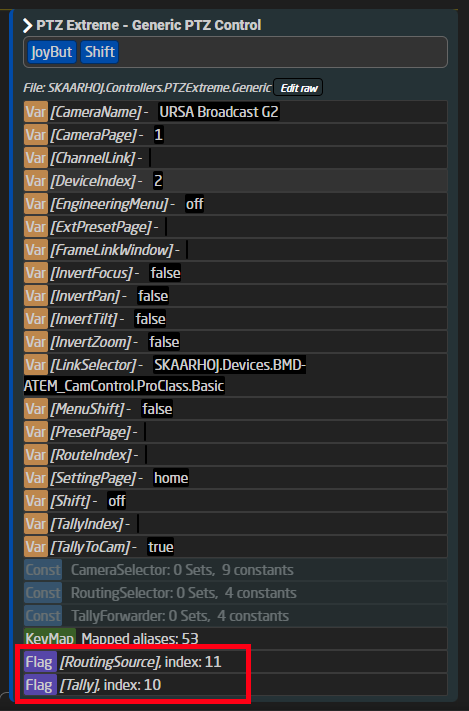
Here is an example from a PTZ Extreme about how these groups are defined on Index 10 and 11:
How to set a flag
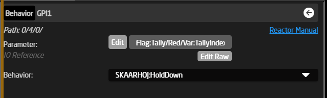
The simplest way to set a flag is to use the normal "SKAARHOJ:HoldDown" behavior on a button/GPI pin or in a virtual trigger where you might use the tally status reported by your switcher.
When setting flags we are looking at an IORefrence structure that looks like this:
Flag:Tally/Red/Var:TallyIndex/
So to break it down we have:
Flag:[Group Name]/[Color]/[Index]
Often you will see us use a variable for the index. In most cases we use it together with a constant set where the user can fill in what routing input or tally index it should follow. For a mixer setup the tally index would correlate with what input number is active on the mixer.
Some examples of this in use
Here is a couple of examples of how these setups look, they are posted here in json format as it's the simplest way to get a condensed look at the setup:
From an RCP using the GPI input to set the red tally flag on the selected camera:
{
"ParentID": "SKAARHOJ:HoldDown",
"IOReference": {
"Raw": "Flag:Tally/Red/Var:TallyIndex"
}
}And here for the preview button (same as pressing the joystick) on the same RCP, that sets a Routing Flag instead:
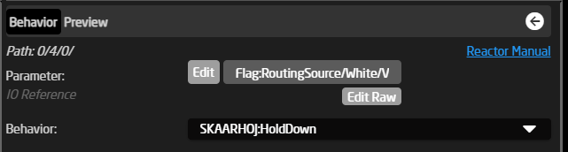
{
"ParentID": "SKAARHOJ:HoldDown",
"IOReference": {
"Raw": "Flag:RoutingSource/White/Var:RouteIndex"
},
"FeedbackDefault": {
"DisplayText": {
"Title": "Preview"
}
}
}A more extreme setup of using a Virtual Trigger for setting the tally flags with tally status from an ATEM mixer:
This is the file you load when you select a tally device in the constant set:
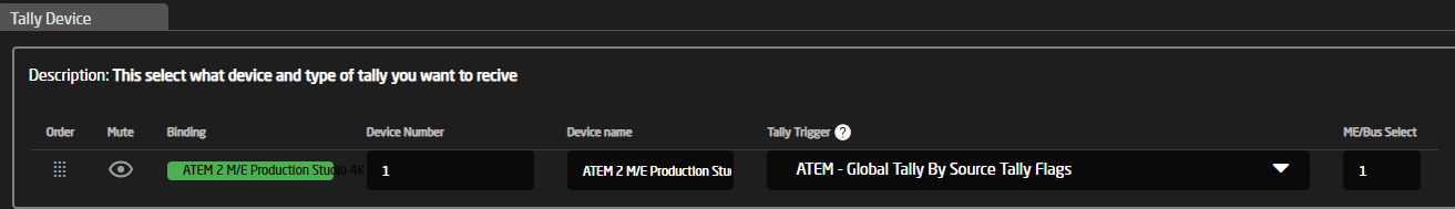
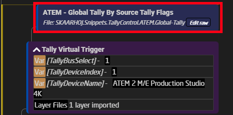
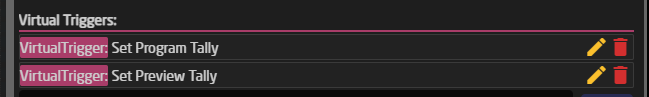
Inside it has two Virtual Triggers that set the Program and Preview Tally and they do the same thing where they read the state of the tally parameter on the ATEM and store it into the flags on either the color red or green, depending on if it's the program or preview tigger.
Full code for the ATEM Tally snippet:
{
"Name": "ATEM - Global Tally By Source Tally Flags",
"MetaData": {
"DeviceCoresInside": {
"bmd-atem": []
},
"Priority": 150
},
"VirtualTriggers": [
{
"Name": "Set Program Tally",
"ConstantSetReference": "CameraSelector",
"Mode": "Binary",
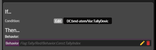
"BinaryActiveIf": "DC:bmd-atem/Var:TallyDeviceIndex/TallyBySourceTallyFlags/Behavior:Const:TallyIndex/1 == true",
"AnalogIOref": {},
"HoldGroupFinalValue": {},
"Behavior": {
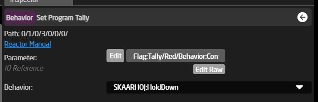
"ParentID": "SKAARHOJ:HoldDown",
"IOReference": {
"Raw": "Flag:Tally/Red/Behavior:Const:TallyIndex"
}
}
},
{
"Name": "Set Preview Tally",
"ConstantSetReference": "CameraSelector",
"Mode": "Binary",
"BinaryActiveIf": "DC:bmd-atem/Var:TallyDeviceIndex/TallyBySourceTallyFlags/Behavior:Const:TallyIndex/2 == true",
"AnalogIOref": {},
"HoldGroupFinalValue": {},
"Behavior": {
"ParentID": "SKAARHOJ:HoldDown",
"IOReference": {
"Raw": "Flag:Tally/Green/Behavior:Const:TallyIndex"
}
}
}
]
}How to read a flag
Reading a flag is very similar to setting a flag, but now we look at the feedback value of it instead and compare it against if it's true or false.
The simplest way to read a flag is to use the "SKAARHOJ:Output" behavior on a LED or GPO pin or in a virtual trigger where you might use the tally status reported by your switcher.
Some examples of this in use
Here is a couple of examples of how these setups look, they are posted here in json format as it's the simplest way to get a condensed look at the setup:
First the simplest way of reading it is for a GPO pin on an RCP for providing routing support externally:
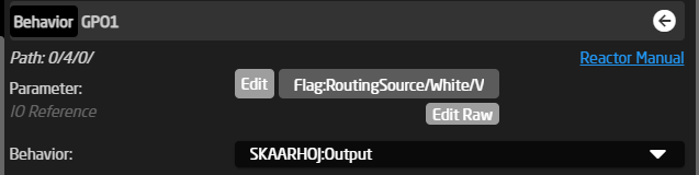
{
"ParentID": "SKAARHOJ:Output",
"IOReference": {
"Raw": "Flag:RoutingSource/White/Var:RouteIndex"
}
}Another use case for a Tally LED on a Blue Pill or RCP where you will see a setup like this, where it reads both the Red and Green Tally bit:
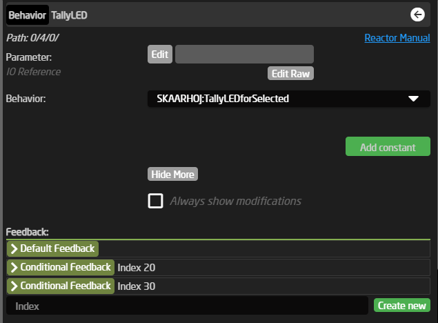
{
"Name": "Tally LED - Selected",
"Description": "Show tally for selected tally index (in TallyIndex variable, using Tally Flag group)",
"IOReference": {},
"FeedbackDefault": {
"Intensity": "Dimmed"
},
"FeedbackConditional": {
"20": {
"ActiveIf": "Flag:Tally/Green/Var:TallyIndex == true",
"Color": {
"ColorCode": "GREEN"
},
"Intensity": "On"
},
"30": {
"ActiveIf": "Flag:Tally/Red/Var:TallyIndex == true",
"Color": {
"ColorCode": "RED"
},
"Intensity": "On"
}
}
}The last two main use cases that we will look at is reading a flag and then sending some command to a BMD Video hub for providing routing control, this is using virtual triggers:
This is the file you load when you select a routing device in the constant set:
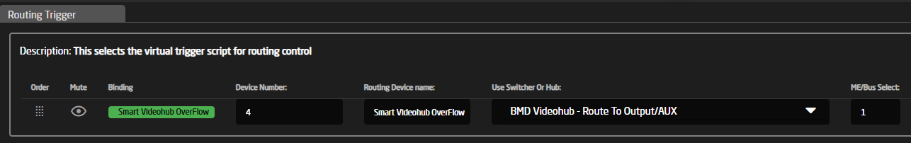
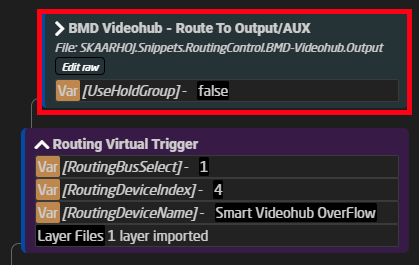
Inside it has virtual triggers that read the stored routing flag and sends the routing selected and sends it to the parameter on the Videohub.

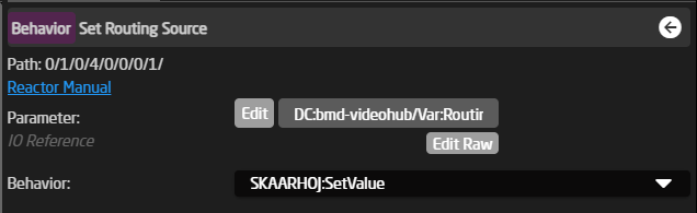
{
"Name": "Basic V-Trigger",
"ActiveIf": "Var:UseHoldGroup:Current == false",
"VirtualTriggers": [
{
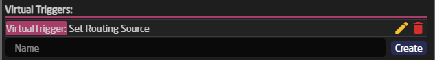
"Name": "Set Routing Source",
"ConstantSetReference": "CameraSelector",
"Mode": "Binary",
"BinaryActiveIf": "Flag:RoutingSource/White/Behavior:Const:RouteIndex == true",
"AnalogIOref": {},
"HoldGroupFinalValue": {},
"Behavior": {
"ParentID": "SKAARHOJ:SetValue",
"IOReference": {
"Raw": "DC:bmd-videohub/Var:RoutingDeviceIndex/routeInputToOutput/Var:RoutingBusSelect"
},
"EventHandlers": {
"trigger": {
"BinarySetValues": {
"Raw": "Behavior:Const:RouteIndex"
},
"IOReference": {}
}
}
}
}
]
}The last main use case to show of here is doing the same as for routing but for forwarding the tally states directly to any camera connected. We will look at the setup for the Canon PTZ cameras in this example:
This example is taken from an ETH-GPIO Link, but it's the exact same code used on all PTZ controllers.
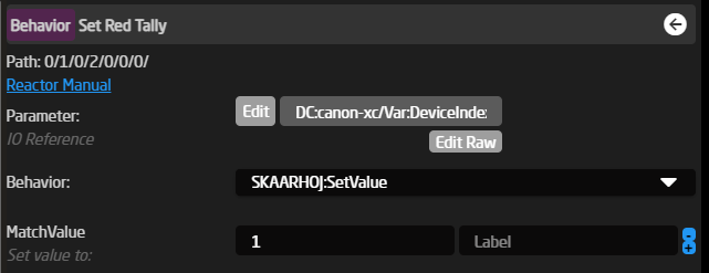
Inside the Camera Selector you will have a field for the "Tally Forward Config", this should auto fill for you and look something like this:
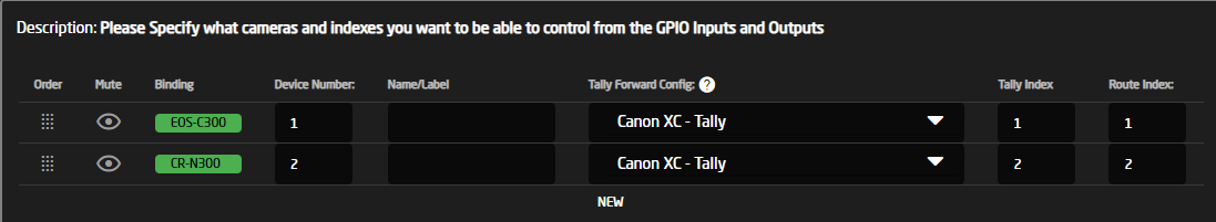
This will then load up like this inside the config, in something that should look familiar by now, as it's the same setup as for the tally and routing setups mentioned above.
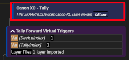
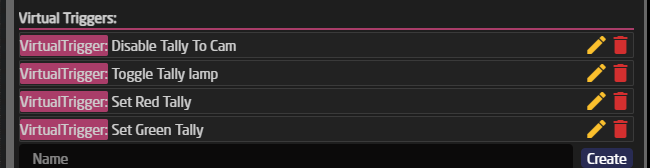
The big difference here is that this setup will very a lot depending on how the cameras handle tally, but one thing they will all have in common is that they have a trigger for disabling tally altogether, and that they all use the same flags, red and green for the tally feedback. On the Canon PTZ's you will see a total of 4 Virtual triggers. We will only look at the "Set Red" trigger.
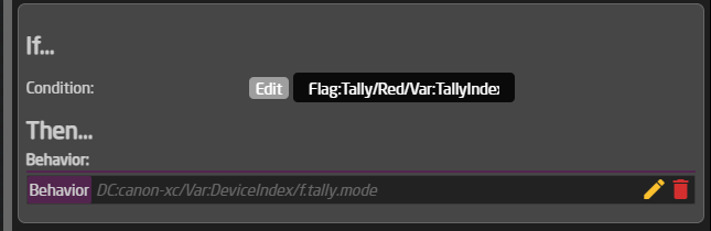
{
"Name": "Set Red Tally",
"ActiveIf": "Var:TallyToCam == true",
"Mode": "Binary",
"BinaryActiveIf": "Flag:Tally/Red/Var:TallyIndex == true",
"AnalogIOref": {},
"HoldGroupFinalValue": {},
"Behavior": {
"ParentID": "SKAARHOJ:SetValue",
"Constants": {
"MatchValue": {
"Values": [
"1"
]
}
},
"IOReference": {
"Raw": "DC:canon-xc/Var:DeviceIndex/f.tally.mode"
}
}
}As seen above, it's basically the same thing the difference is only that here we have a "MatchValue" to select that it's the program we want to set on the Canon PTZ, if we want to swap the colors on the PTZ, then it's just a matter of changing this from a 1 to a number 2 and the reverse on the preview trigger. This is because of the options available on the camera, to look more at these option please refer to the parameter list for the Canon-XC core.
Here is the full JSON for this layer with all 4 virtual triggers, in their current form:
{
"Name": "Canon XC - Tally",
"MetaData": {
"DeviceCoresInside": {
"canon-xc": []
},
"Priority": 100
},
"VirtualTriggers": [
{
"Name": "Disable Tally To Cam",
"Mode": "Binary",
"BinaryActiveIf": "Var:TallyToCam == false",
"AnalogIOref": {},
"HoldGroupFinalValue": {},
"Behavior": {
"ParentID": "SKAARHOJ:SetValue",
"Constants": {
"MatchValue": {
"Values": [
"0"
]
}
},
"IOReference": {
"Raw": "DC:canon-xc/Var:DeviceIndex/f.tally"
}
}
},
{
"Name": "Toggle Tally lamp",
"ActiveIf": "Var:TallyToCam == true",
"Mode": "Binary",
"BinaryActiveIf": "Flag:Tally/Red/Var:TallyIndex == true || Flag:Tally/Green/Var:TallyIndex == true",
"AnalogIOref": {},
"HoldGroupFinalValue": {},
"Behavior": {
"ParentID": "SKAARHOJ:HoldDown",
"IOReference": {
"Raw": "DC:canon-xc/Var:DeviceIndex/f.tally"
}
}
},
{
"Name": "Set Red Tally",
"ActiveIf": "Var:TallyToCam == true",
"Mode": "Binary",
"BinaryActiveIf": "Flag:Tally/Red/Var:TallyIndex == true",
"AnalogIOref": {},
"HoldGroupFinalValue": {},
"Behavior": {
"ParentID": "SKAARHOJ:SetValue",
"Constants": {
"MatchValue": {
"Values": [
"1"
]
}
},
"IOReference": {
"Raw": "DC:canon-xc/Var:DeviceIndex/f.tally.mode"
}
}
},
{
"Name": "Set Green Tally",
"ActiveIf": "Var:TallyToCam == true",
"Mode": "Binary",
"BinaryActiveIf": "Flag:Tally/Green/Var:TallyIndex == true && Flag:Tally/Red/Var:TallyIndex == false",
"AnalogIOref": {},
"HoldGroupFinalValue": {},
"Behavior": {
"ParentID": "SKAARHOJ:SetValue",
"Constants": {
"MatchValue": {
"Values": [
"0"
]
}
},
"IOReference": {
"Raw": "DC:canon-xc/Var:DeviceIndex/f.tally.mode"
}
}
}
]
}Flags used in Routing Triggers
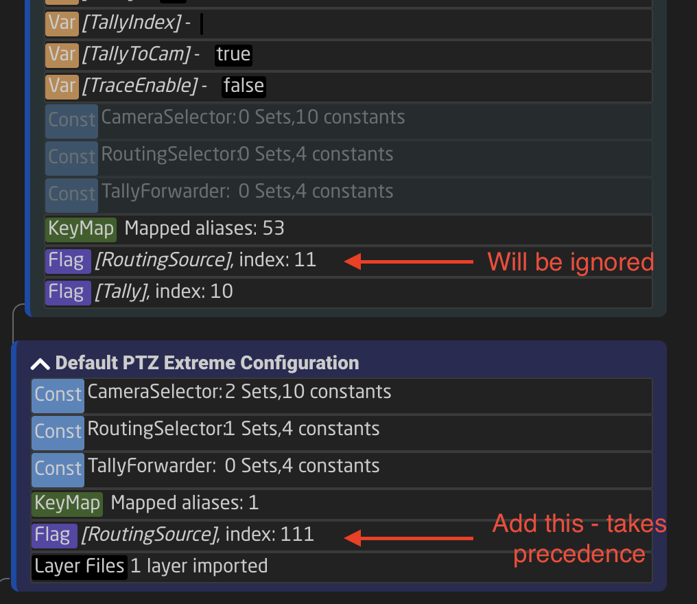
Routing Triggers in SKAARHOJ PTZ Controller configurations utilize a flag named "RoutingSource". This flag is used to communicate between the camera selector and a virtual trigger, providing information about the input source to be routed to a specific video switcher or hub when a camera is selected. The "RoutingSource" flag index varies across different controller configurations. For instance, the index for a PTZ Extreme is set to "11":
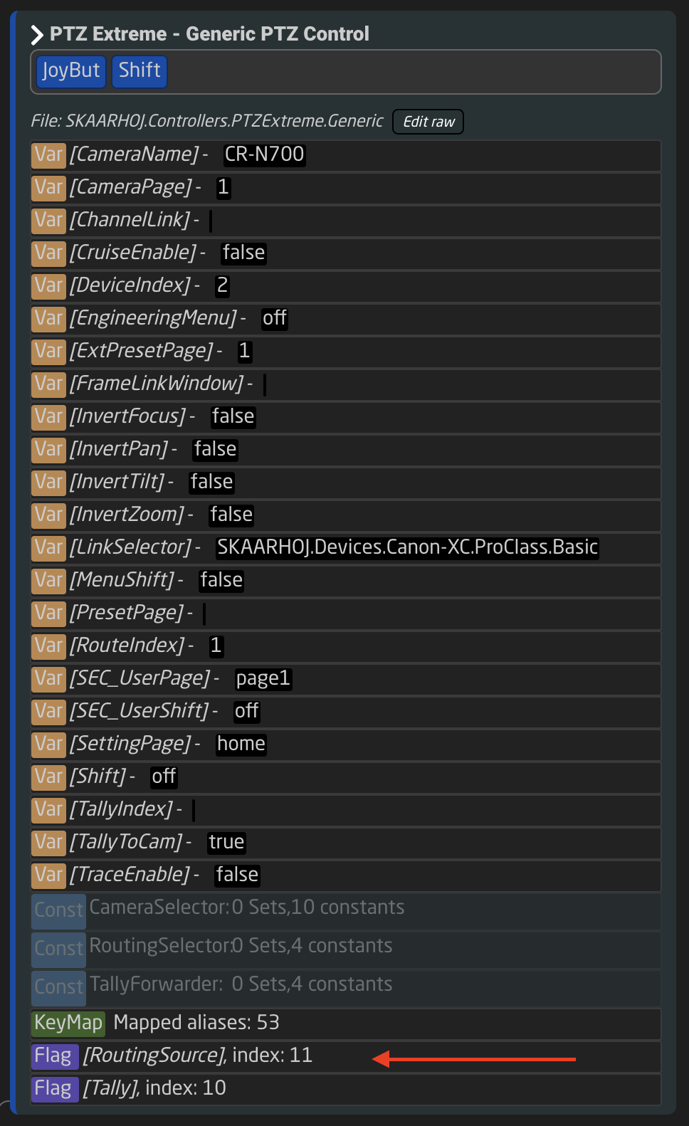
When managing multiple PTZ Extremes with the same configuration, a conflict arises as each controller's Routing Trigger setup uses the same index (11). This duplication can lead to operational issues. That same is true for other controllers and their configurations being shared.
Solution to the Index Conflict
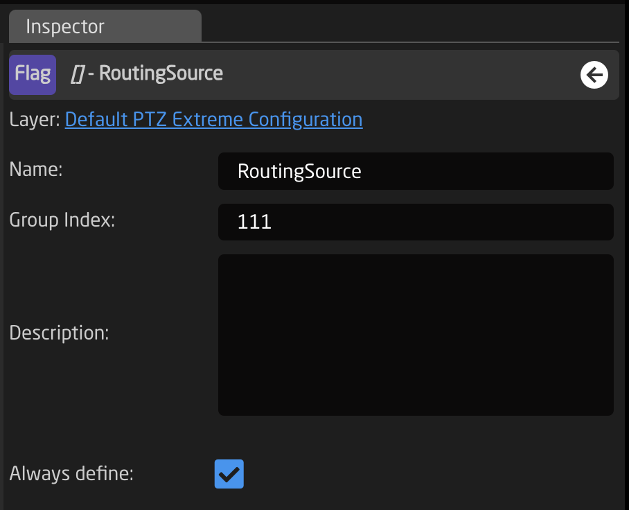
The solution lies in creating a flag by the same name in the tree on a parent layer to the shared configuration. The "RoutingSource" flag (a "TreeDweller" property in the configuration tree) is not set with the "Always Define" flag. This allows for an alternate definition of "RoutingSource" on the parent layer of the configuration. When defined on this parent layer, it prevents the value inside the PTZ Extreme Configuration from overriding. Thus, for any additional configurations of similar controllers, you can assign a different index number to the "RoutingSource" flag by setting it on the parent layer. See below:
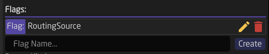
Adding a new flag is done from the tree by clicking the layer name and adding a flag in the Inspector:
Variables
This documentation might be outdated. Please consult the Reactor manual at https://docs.skaarhoj.com/3_configuration/variables-conditions.html
For increased flexibility in a configuration Variables are often applied. A variable works as an adjustable value which can be numerical or text based that can be used in place of a set value.
Variables live on the layers of the tree but are used in lots of different places and in different ways. It is on the layers that you can see what Variables are available, their names, and their current value. In the example below you can see how:

Please note, Variables in the tree are only accessible to the same layer they are created on or higher in the tree, unless defined otherwise in the variable set up. Additionally, layers limited by Active If conditions also set limits on the variable.
There are two types of variables; range or options.
Range Variables

| Name | Variable's name |
| Description | Easy to understand description to help identify the variable's purpose |
| Type | Range or Options |
| Min | Minimum value for the variable (must be lower than the max). Can be set to 0 |
| Max | Maximum value for the variable (must be higher than the max) |
| Center (or Default) | Default value for the variable if not saved on panel reboot. |

| Default to first | Sets default value to the first. |
| Default Value | Define the default value if not first. |
| Always define | Separates this instance of the variable from ones of the same name lower in the tree (overridden by Expand Scope). |
| Accept Any Value | Allows any value to be accepted during conformity check. |
| Expand Scope | Allows the variable to be used lower in the tree towards the root. |
| Capture | Allows a variable to capture any expanded-scope variable from a branch. |
| Persistent | Saves value between panel reboots. |
| Zero set Allow | Allows for the variable to be blank |
| Force value (test) | Force set a value for the variable, use for testing |
Variable Use Case
Range variables are great for creating dynamic device parameters. In the example below, the variable is set within a parameter.
This is only a single example of the use of Options Variables.
First looking at a breakdown of the parameter the variable is going to be added into: Atem Program Input Video Source
DC:bmd-atem/1/ProgramInputVideoSource/1/1
DC (DEVICE CORE) :bmd-atem (BMD-ATEM) /1 (DEVICE ID 1) /ProgramInputVideoSource (Specified parameter)
/1 (M/E number) /1 (Input Number)
A range variable would most naturally be put in place of numerical values, making Device ID, M/E Number, or Input Number great places use a variable. Using the variable in place of the Device ID will allow for switching instances of the Atem.
It is possible to find the specific Device ID number of the Atems in the Device Details on the Home Page of Reactor.

When creating the variable it is best to name is something easy to identify the place it should be used. 
Insetting that variable in the command would look like this:
DC:bmd-atem/Var:DeviceIndex/ProgramInputVideoSource/1/1
Please note: Formatting is important for the variable name.
After setting the variable into a parameter it is important to set up a way to control the variable.

The feedback will look like:

Confirm the variable is changing properly in the tree:

Options Variable
Variable Set Up
| Name | Variable's name |
| Description | Easy to understand description to help identify the variable's purpose |
| Type | Range or Options |
| Value | Value string for the variable |
| Label | Easy to understand label used for feedback |
| Flag | Sets the option as the default value |
| Trash | Deletes the Option |
| Duplicate | Duplicates the line |
| +1 | Increments the line by +1 |
| Add option | Default value for the variable if not saved on panel reboot. |

| Default to first | Sets default value to the first. |
| Default Value | Define the default value if not first. |
| Always define | Separates this instance of the variable from ones of the same name lower in the tree (overridden by Expand Scope). |
| Accept Any Value | Allows any value to be accepted during conformity check. |
| Expand Scope | Allows the variable to be used lower in the tree towards the root. |
| Capture | Allows a variable to capture any expanded-scope variable from a branch. |
| Persistent | Saves value between panel reboots. |
| Zero set Allow | Allows for the variable to be blank |
| Force value (test) | Force set a value for the variable, use for testing |
Variable Use Case
Options variables are great for Active If conditions on layers of the tree. In the example below, the variable is set up to make active different page layers in the tree.
This is only a single example of the use of Options Variables.

In the tree it would look like this. The blue line next to a layer indicates it is the active layer. In the layer where the variable lives, the variable also shows what its current value is.

On the page layer, the variable is set as the Active If conditions, meaning that need to be true for the layer to be the active layer.

There are two main way to select the value of the parameter.
To set a specific value, mainly on key press or by trigger, select the variable as a parameter with the Settings Template as Set a Value Directly.

The feedback will look like this:

To cycle through the values, mainly on the pulse of an encoder, select the variable as a parameter with the Settings Template as Change Variable.

The feedback will look like this:

Virtual Triggers
This documentation might be outdated. Please consult the Reactor manual at https://docs.skaarhoj.com/3_configuration/virtual-triggers.html
Sometimes you want to create interaction between devices using Reactor, or use the state of a device to change Variables in the system (eg changing the visible layer depending on the currently active camera)
This is what Virtual Triggers are for, providing the ability to use Conditions and Values of Devicecores to change other values in the system or even on other devices
Virtual Triggers in Reactor can be created on Layers in the Configurator and have 3 modes:
|
Binary |
Analog |
Schedule |
|
In Binary mode a condition will be interpreted like a Binary trigger (basically imitating a button). While the condition is true the VirtualTrigger is "pressed" and while its false it is "released" |
In Analog mode the selected parameter becomes an Analog Trigger (basically imitating a fader). Everytime the value is changed a new Analog Value is sent to the defined Behavior |
In Schedule mode you can configure a schedule of when your trigger will be executed using cron like syntax. Everytime the specified time is reached the Virtual trigger will send a Binary trigger (basically a buttonpress) to the defined behavior |
Cron explained
Cron is a UNIX utility that schedules a command or script on your server to run automatically at a specified time and date.
Not only does it allow for precise timing of unattended events, but it has a straightforward syntax
| * | * | * | * | * | * | |
| Field name | Seconds | Minutes | Hours | Day of month | Month | Day of week |
| Allowed values | 0-59 | 0-59 | 0-23 | 1-31 | 1-12 or JAN-DEC |
0-6 or SUN-SAT |
| Allowed special characters | * / , - | * / , - | * / , - | * / , - ? | * / , - | * / , - ? |
All 6 points of information is required.
Allowed special characters explained:
Asterisk ( * )
The asterisk indicates that the cron expression will match for all values of the field; e.g., using an asterisk in the 5th field (month) would indicate every month.
Slash ( / )
Slashes are used to describe increments of ranges. For example 3-59/15 in the 1st field (minutes) would indicate the 3rd minute of the hour and every 15 minutes thereafter. The form "*\/..." is equivalent to the form "first-last/...", that is, an increment over the largest possible range of the field. The form "N/..." is accepted as meaning "N-MAX/...", that is, starting at N, use the increment until the end of that specific range. It does not wrap around.
Comma ( , )
Commas are used to separate items of a list. For example, using "MON,WED,FRI" in the 5th field (day of week) would mean Mondays, Wednesdays and Fridays.
Hyphen ( - )
Hyphens are used to define ranges. For example, 9-17 would indicate every hour between 9am and 5pm inclusive.
Question mark ( ? )
Question mark may be used instead of '*' for leaving either day-of-month or day-of-week blank.
Alternatively we also allow these inputs:
| Entry | Description | Equivalent To |
| @yearly (or @annually) | Run once a year, midnight, Jan. 1st | 0 0 0 1 1 * |
| @monthly | Run once a month, midnight, first of month | 0 0 0 1 * * |
| @weekly | Run once a week, midnight between Sat/Sun | 0 0 0 * * 0 |
| @daily (or @midnight) | Run once a day, midnight | 0 0 0 * * * |
| @hourly | Run once an hour, beginning of hour | 0 0 * * * * |
Videos
In these videos Kasper shows some examples of how to work with Virtual Triggers.