Blue Pill Inside (BPI) - Getting Started
Step by step guide to initial set up of a Blue Pill Inside device.
- Networking
- Accessing Blue Pill
- Select Configuration
- Adding Devices
- Populating Settings Tables
- Watch Youtube videos
Networking
Unlike UniSketch where a change of configuration and included device cores needed an online exchange with the SKAARHOJ server, on Blue Pill everything is stored and enabled and disabled locally in Reactor. Only software updates or installations of non-existing device cores and applications need communication with the SKAARHOJ server over the internet. All changes in configurations can be done via the local network.
Network Requirements
- SKAARHOJ Blue Pill controllers have a 1 GBit network interface
- 5W-30W PoE (+)
- PoE Standard: IEEE 802.3af/t
Remember a SKAARHOJ controller and client must be on the same subnet (192.168.10.* or one defined for the local network used by the controller). With multiple SKAARHOJ units connected to the same network they need to have different IP addresses!
Power over Ethernet (PoE) Specifications
We use the PoE industry standard 5W-30W PoE (+) IEEE802.3af7t. To power our controllers using PoE it is important the switch supports this standard. Please notice some manufactures such as Ubiquity have their own non-standard 24V type of PoE which is incompatible with our controllers. Especially pay attention to the standard when using a PoE injector.
Network Layout
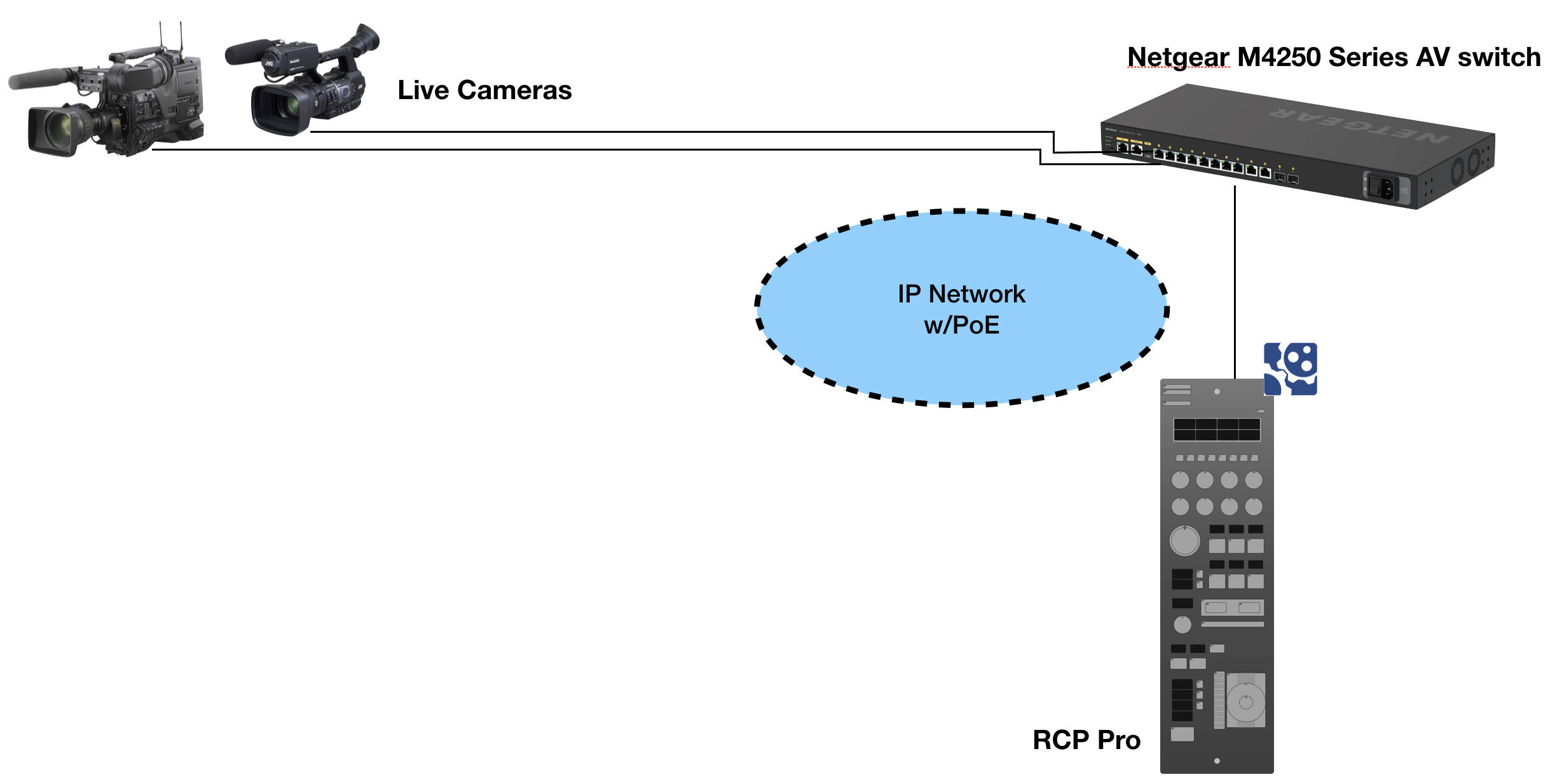
We recommend connecting SKAARHOJ Blue Pill controllers via professional PoE network switches, such as NetGears M4250-series which are at the same time designed for AV network traffic such as NDI video.
A RCP Pro and cameras configuration could look like this:
Please note, we are not networking experts and are not able to assist in network set up.
Accessing Blue Pill
DHCP or Static IP
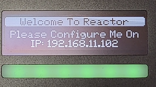
The Blue Pill’s user interface is accessed via the device’s IP Address and any web browser. The IP address can be found on the display after it is plugged into a network connection with PoE or a network connection and a power supply (5V Micro USB). By default the Blue Pill should get an IP address via DHCP, if that fails it should fallback to 192.168.10.99.
Entering the IP address into the address bar of a search engine will bring up a prompt for username and password. The default is username: admin password: skaarhoj
Please note that by signing in you are accepting the terms of the user agreement.

Link from SKAARHOJ Discovery App
If the SKAARHOJ Discovery open on a computer running on the same subnet as the Blue Pill, the Blue Pill should appear below the main controller access buttons of the updater. Clicking on Configure next to the panel’s information will open the web interface directly. The Blue Pill does not need to be connected to the computer via USB.

SKAARHOJ Discovery and Micro USB
If a network connection to the Blue Pill in not available, the IP address can be set using a Micro USB cable. In this case the Blue Pill will appear in the “On USB” tab in the Discovery App can be used to set the IP address:

It is possible to toggle between DHCP and Static IP. After setting the IP address, Subnet Mask, and Gateway, press Update to apply.

Wi-Fi Access Point
If the Blue Pill is not displaying an IP address, the web interface is accessible by enabling the internal Wi-Fi access point.
To enable the Wi-Fi access point, gently press and hold the config button on the Blue Pill device for about 3 seconds (see image below). Use a flat screw driver, a paper clip or similar - you should feel the springy button-click when pushing it.
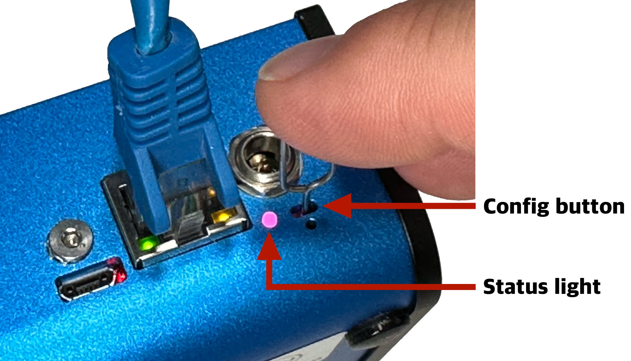
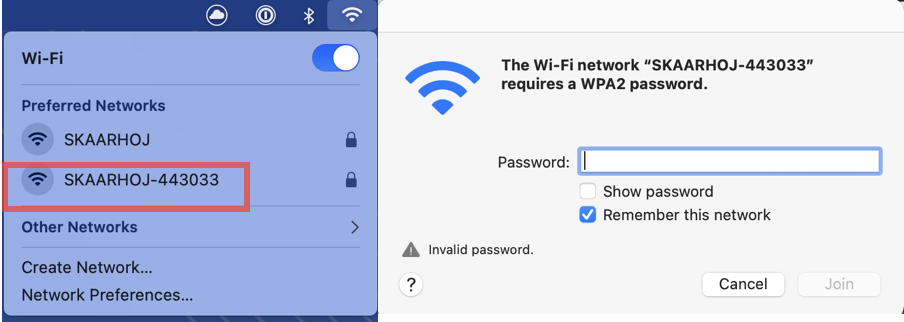
After holding Config button for 3 seconds the internal Wi-Fi Access Point is enabled and the Status LED will light up purple. It will show up in the Wi-Fi networks list as SKAARHOJ-XXXXXX (Blue Pill’s serial number).
The default password is: skaarhoj
The web interface is then accessed at the IP address: 192.168.4.1
After accessing the Blue Pill it is best to navigate to the System/Settings page to set a static IP address. Once saved, the new IP address will appear on the Blue Pill’s display, it may be necessary to reboot or power cycle the device afterwards.

Using Legacy Skaarhoj Firmware Updater Application
Link from SKAARHOJ Firmware Updater
If the SKAARHOJ Firmware Updater open on a computer running on the same subnet as the Blue Pill, the Blue Pill should appear below the main controller access buttons of the updater. Clicking on Configure next to the panel’s information will open the web interface directly. The Blue Pill does not need to be connected to the computer via USB. 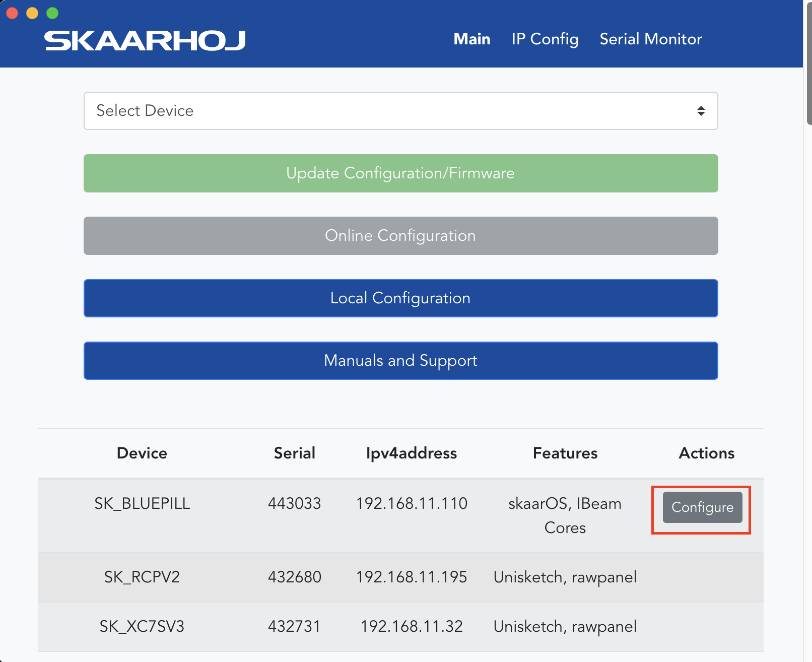
SKAARHOJ Firmware Updater and Micro USB
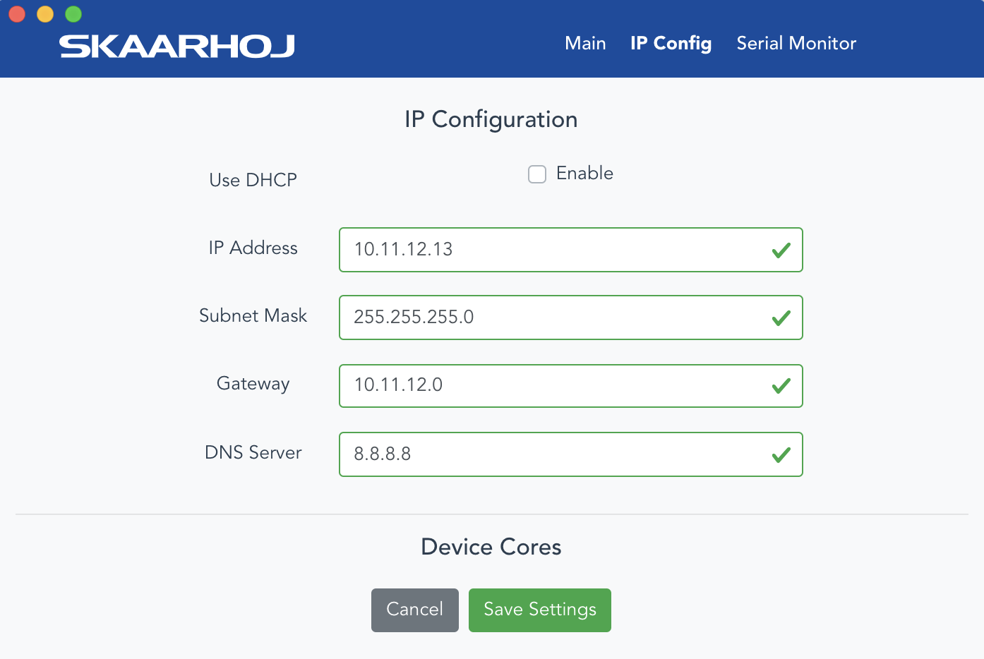
If a network connection to the Blue Pill in not available, the IP address can be set using a Micro USB cable. In this case the Blue Pill will appear in the “Select Device” dropdown and the “IP Config” tab in the Firmware Updater can be used to set the IP address (same procedure from UniSketch):
In this case it was identified as “/dev/tty.usbmodem4430361” (on MacOS) and pressing IP Config will open the IP set up page:
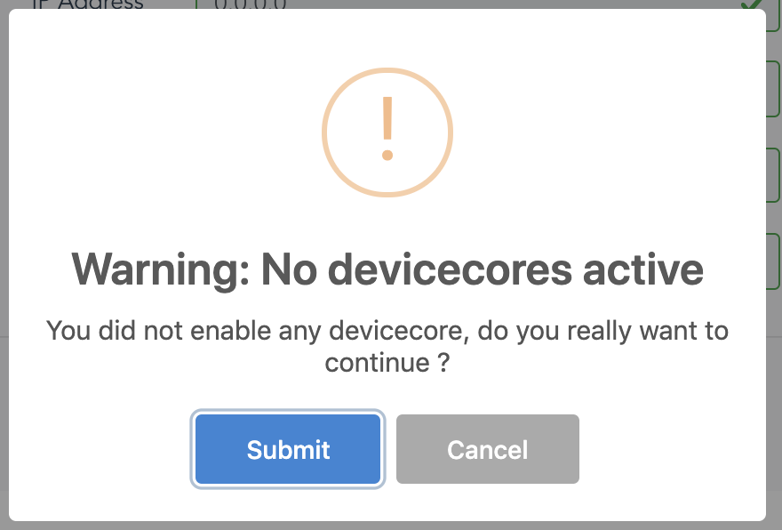
If/When the warning below appears, press “Submit” and reboot the Blue Pill:
Select Configuration
The controller’s layout is determined by the configuration. In most cases, the Generic configuration is all that is needed, though for some combinations of panel and device, there are specific configurations.
The configuration is chosen in the drop down next to the panel.

Adding Devices
There are two main ways a device can be added to a new Blue Pill, Auto Discover and Manually.

Auto Discover
Searching on the network for devices will find many types by a combination of mDNS look-ups and other methods. However, not all devices can be discovered easily, but with those that can, it’s a simple click of a button to add it to the Blue Pill device collection. Following an Auto Discover some device details may still be needed to establish connectivity. See Device Details section for set up.

Pressing SHIFT + the green Select button will allow for multiple device selection.
Manually Added
If a device must be added manually, it’s easy to look it up in the list of supported models. Following a manual choice of device, the user will have to enter the IP address and other possible device detail information. See the Device Details section for set up.

Pressing SHIFT + the green Add Device button will allow for multiple device selection.
Device Details
Devices have their status displayed clearly in the overviews on the Home screen.
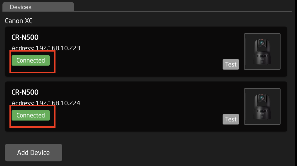
Clicking on a device name in the Devices section will open up the details. Here the name, ID number, and Active status of the devices can be changed. By default the device name will be the same as the model name, the ID will be auto generated in order, and the status will be active. When applicable to the device, the option for connecting is a specific username and password will also be available along with other device specific options. Without setting a specific username and password, in most cases the core will try to connect to the device’s default username and password.
A device needs to be set to Active for use.

Populating Settings Tables
The final step is to fill in any settings table. The settings tables are available based on the chosen configuration and should contain entries such as specific cameras for a PTZ controller, or the inputs for a video switcher etc. They can be found in a large number of our configurations.
The settings tables will auto save and quickly appear on displays and enable the function.
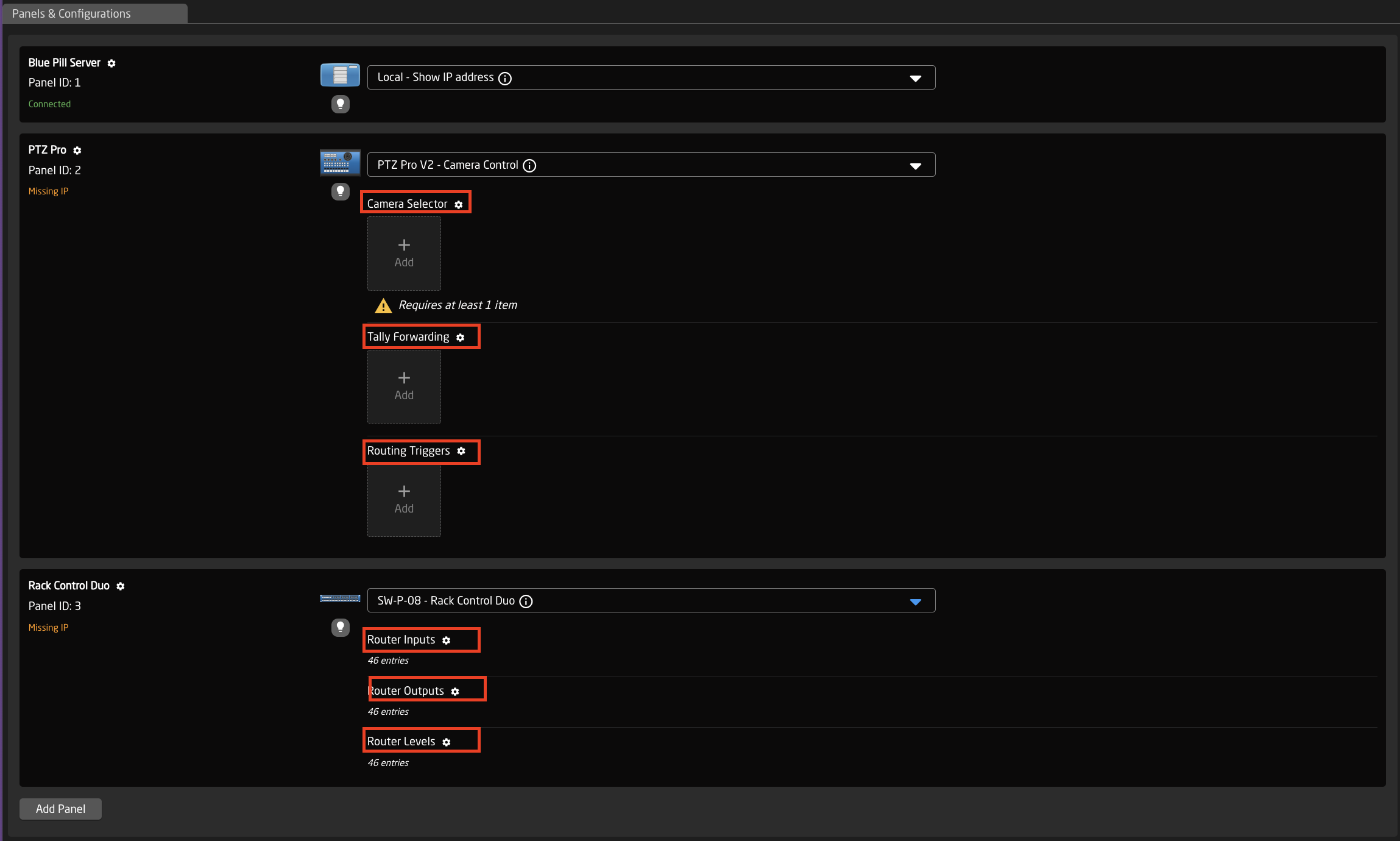
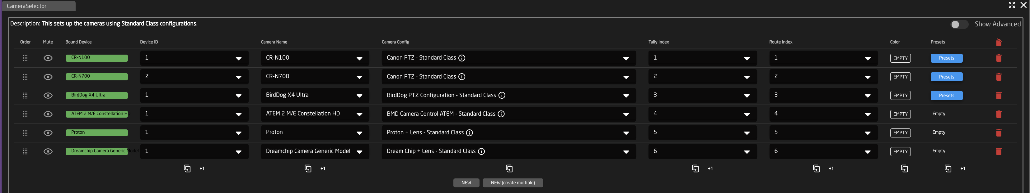
An example of a settings table would be a camera selector and can be seen below. These can be different depending on the selected configuration. From here the order on the camera selector row of the panel will be set as well as the desired name on the displays.
|
Column |
Description |
|
Order |
Allows for quick rearranging of camera order. Right clicking on drag will allow for deleting the row. |
|
Mute |
Allows for removing access to a specific camera or to leave a blank spot on the panel |
|
Bound Device |
Allows for the selecting of a specific connected camera |
|
Device ID |
Ties the camera selector to the specific device. This is found in the Devices section. Each device will have a unique device number per device core. This box should auto-populate when a camera is selected in binding |
|
Camera Name |
Customizable name to appear on the displays. Character limit is determined by size of display and can vary. |
|
Camera Config |
Selects the protocol based configuration associated with camera. Needed protocol can be seen in the Devices section, each device is grouped into their native protocols. Double check the correct configuration is selected. Improper selection will effect camera control. |
| Tally Index | Sets the Tally Index number to connect with associated tally source device. See Blue Pill/Reactor Manual for more information. This column does not need to be filled out for standard operation. |
|
Route Index |
Sets the Route Index number to connect with associated routing device. See Blue Pill/Reactor Manual for more information. This column does not need to be filled out for standard operation. |
|
Color |
Sets the button color for the associated camera select button. This column does not need to be filled out for standard operation. |
|
Presets |
Allows for the setting of preset names for applicable configurations. This column does not need to be filled out for standard operation. |
|
|
Deletes the row. |
Watch Youtube videos
In addition to our written guides, you can also watch our Youtube videos on how to get started.
• Get Started with Blue Pill Inside products
https://youtu.be/VtdJ9xVu3qA
• Get started with Blue Pill Server
https://youtu.be/EROUURQU9pE
• Reactor overview
https://youtu.be/dAPuzK6G5AQ
• How to change IP address
https://youtu.be/tr8ucKOvuAE
• Access without DHCP <-- old version of 'How to change IP address'
https://youtu.be/59d2fc1kAuQ
• Manage and Backup Projects
https://youtu.be/npju0vfzCSw