| **1** | USB-A Port. See Settings page for more details |
| **2** | SKAARHOJ Expansion Slot |
| **3** | HDMI Port serial diagnostics and debugging |
| **4** | Config Button to enable WiFi Access Point. See Accessing Blue Pill section in Getting Started Guide |
| **5** | Status LED for monitoring and debugging. See below for more information. |
| **6** | IP Network RJ45 Port for IP control and 5W-30W PoE (+)/PoE Standard: IEEE 802.3af/t |
| **7** | Micro USB Port for serial communication and 5V power |
| **1** | Micro USB Port for serial communication with SKAARHOJ Firmware Updater |
| **2** | IP Network RJ45 Port for IP control and 5W-30W PoE (+)/PoE Standard: IEEE 802.3af/t |
| **3** | Status LED for monitoring and debugging (see below) |
| **4** | Not used |
| **5** | Config Button (see below) |
| **6** | 12V DC Power Supply for connection to the supplied DC power adaptor |
| **7** | USB-A Port. See Settings page for more details, not available on all models |
GPI is an add on option for the Color Fly v3B, it does not come standard.
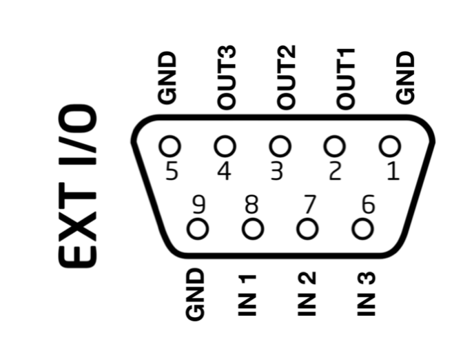
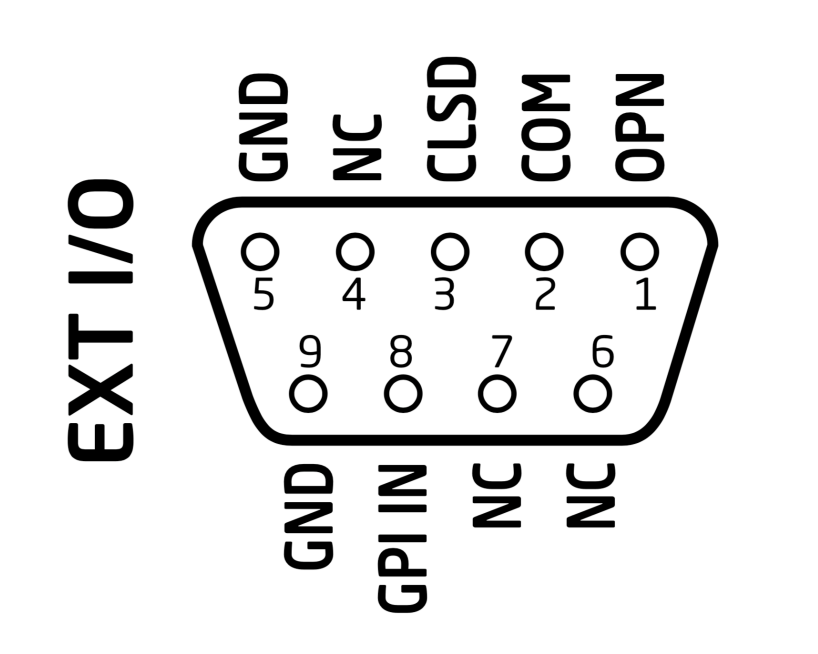
**[](https://wiki.skaarhoj.com/uploads/images/gallery/2022-10/eth-gpi.png)** **RCP Pro DB-9 Connector**The RCP Pro only has 3x GPI Input and 3x GPI Outputs that are programmable, this is different than the RCPv2.
**[](https://wiki.skaarhoj.com/uploads/images/gallery/2022-10/db15-connector.png)** **3G SDI Arduino Shield**SDI is an add on option for the Color Fly v3B, it does not come standard.
**[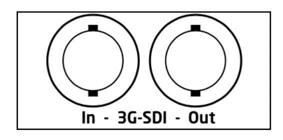](https://wiki.skaarhoj.com/uploads/images/gallery/2022-10/sdi.png)**The Blackmagic 3G-SDI Arduino Shield supports the following formats using SDI Level B: 720p50, 720p59.94, 720p60, 1080i50, 1080i59.94, 1080i60, 1080p23.98, 1080p24, 1080p25, 1080p29.97, 1080p30, 1080p50 (output only), 1080p59.94 (output only) and 1080p60 (output only), but the camera doesn't have to be running the same video format as the program input, so you can use cameras in Ultra HD while the camera protocol is sent over HD signal to the camera. # Graphical Displays **Graphical Display** The Blue Pill has a graphical LED Display. By default this is set to go into a sleep mode to prevent image burn-in. The unit is still operational during sleep mode, it is only the display that effected. Burn-In caused after disabling sleep mode is not covered by our standard warranty. To wake the Blue Pill up from sleep mode, it should only be necessary to tap the unit. It is not necessary to shake it like a polaroid picture. # Operating Temperatures **Operating Temperature:** 0° C to +40° C / +32° F to +104° F **Max Internal Temperature:** 80°C / 176°F **Storage Temperature:** -20° C to +45° C / -4° F to +113° F **Humidity:** 90\\% RH, non-condensing, from -20° C to +45° C The Blue Pill device’s internal processes statics is accessible by following the instructions on our wiki page: [https://wiki.skaarhoj.com/books/blue-pill-reactor/page/internal-processes-stats](https://wiki.skaarhoj.com/books/blue-pill-reactor/page/internal-processes-stats) # Power over Ethernet (PoE) Specifications **Power over Ethernet (PoE) Specifications** We use the PoE industry standard 5W-30W PoE (+) IEEE802.3af/t. To power our controllers using PoE it is important the switch supports this standard. Please notice some manufactures such as Ubiquity have their own non-standard 24V type of PoE which is incompatible with our controllers. Especially pay attention to the standard when using a PoE injector. # UniSketch Panel ConnectionsFor full UniSketch panel guide see the UniSketch Installation and Operations Manual here: [https://github.com/SKAARHOJ/Support/blob/master/Manuals/SKAARHOJ/SKAARHOJ\_Manual.pdf](https://github.com/SKAARHOJ/Support/blob/master/Manuals/SKAARHOJ/SKAARHOJ_Manual.pdf)
#### **Back Panel Connection** 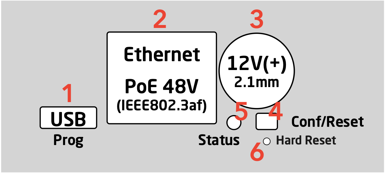 **1. Micro USB plug.** Used for service monitoring and programming new software into the unit (firmware upgrades). **2. Ethernet Jack.** Connect this to your ethernet switch. This jack may also support PoE (Power over Ethernet) if your SKAARHOJ controller was delivered with that option. When connected to a network switch, the yellow LED (lower left) will be on. When data is sent to/from the controller, the green LED (lower right) will blink. If the device in the other end supports TX/RX auto detection you may be able to connect the SKAARHOJ controller directly to your device, otherwise use a crossed cable or a network switch (the supported setup). **3. DC input.** Use a standard 2.1mm center pin plug (center = ”+”). Allowed voltage range is 7-18V. We test controllers will work at 12V. The device uses max 1A at 12V. Units with Blackmagic 3G-SDI Arduino Shields needs 12V. **4. Configuration/Reset button.** Use a pencil or tooth pick to press the button. When you press the button shortly, the controller will reset (same as pulling the power plug). If you press and hold the button, you can reset the controller into configuration mode (as as pressing “Local Configuration” in Firmware Application): A. Press and hold the button until the status LED becomes blue after a few seconds. Release the button and the controller is in *config* mode. You can access the controller web interface with a web browser on ”http://\[CONTROLLER IP\]/” where CONTROLLER IP is the IP address used for the currently loaded preset. The controller will run a diagnostics mode after 2 minutes where displays and buttons will light up. B. Press and hold the button longer until the status LED becomes white (which is 2 seconds after becoming blue). Release the button and the controller is in config default mode. You can access the controller web interface with a web browser on ”http://192.168.10.99/”. The controller will immediately run a diagnostics mode where displays and buttons will light up. C. Press and hold the button even longer until the status LED becomes red (which is 10 seconds after becoming blue and 8 seconds after becoming white). This will clear all presets in memory thereby resetting all configuration made in the controllers own web interface (this corresponds to the serial monitor command “clearpresets” and should only be necessary in case a firmware update requires it or if there is another tricky error state present). In rare cases you cannot rely on the reset button but have to turn off the power to the controller instead (“cold start”). **5. Status LED:** When the controller is just powered up, you will see the status LED blink purple during the boot process. In this process, the hardware is initialized. Eventually the LED should end up blinking slowly (2 sec period) steady green (or blue or white if in config modes). If the LED blinks yellow quickly it indicates that connection to one or more devices is not established. This is perfectly normal for a few seconds between the boot up process (purple blinks) and the operational state (green blinks) when the controller connects to all devices. The status LED should never be permanently on or off, this indicates a potential freeze in the system. In fact, in normal healthy operation the LED should blink with a steady 2 sec period, otherwise it could indicate trouble with connections or hardware. The LED will also light up red for a split second whenever an analog hardware component (such as a T-bar) is operated (this feature is helpful to determine if calibration is needed). **6. Programming Mode Reset:** Will make a hard reset of the controller leaving it with *no* firmware. Is used if the controller does not appear in the Port list in the Firmware Application. Only to be used prior to have consulted SKAARHOJ Support. Please see section: Controller does not show up under Port in Firmware Application. #### **Status Light Overview** **Purple blinks, uneven durations** The controller is booting up (and for each blink a given step has been completed). **Yellow blinks, quickly** The controller hasn't established necessary connection to one or more devices. At the end of the boot process this is natural for a few seconds as the controller connects to devices for the first time. If you unplug the network cable or turn off an external device the controller is connected to, you will also see this state. Just turn on the external device again or re-insert the cable and the error state should restore itself to normal operation (green, steady blinking) after some time. If this happens during normal operation and without obvious explanations (like removal of a network cable or shutting down an external device), it's an error state you need to pay attention to and bug-fix further. If the controller boots up and never stops blinking yellow, you may want to check if you have configured devices for the controller which are not currently present in the network set up. Go to config mode, enter the web interface and check which devices are enabled and their IP addresses. **Green blinks, steady, period of 2 seconds** Normal mode, everything is connected and working properly. Just bliss **Blue or white blinks, steady, period of 2 seconds** Config mode (white: “config default”) where you can access the controller web interface. **Red blinks (interrupting green or yellow blinks)** This happens if you move an analog hardware interface component like a T-bar or knob and is totally normal in that case. However if such blinks happen without you touching any analog components it indicates the need for calibration. **Quick red blinks and no response from controller** A problem with the preset memory checksum indicates that the preset memory may be corrupt. However, in most cases a “cold start” by removing the power supply, waiting 10 seconds and connecting the power supply will solve the problem. If after 2-3 attemps with this solution it still remains a problem, you must clear the preset memory. This is done by holding the config button pressed, then apply power to the controller and wait for around 15 seconds until the status LED becoems solid red (before that state, the LED should be first purple, then blue, then white for 8 seconds and finally solid red). When the LED is red, release the button and the status LED should start blinking again and the controller should boot up. Notice that your controller will be reset to factory settings in this case and you may need to reload or recreate your configuration. #### **3G SDI Arduino Shield**The 3G SDI Arduino Shield imbedded in UniSketch panels is not compatible when using the UniSketch panel with a Blue Pill device. It will only function when working only via the UniSketch platform.
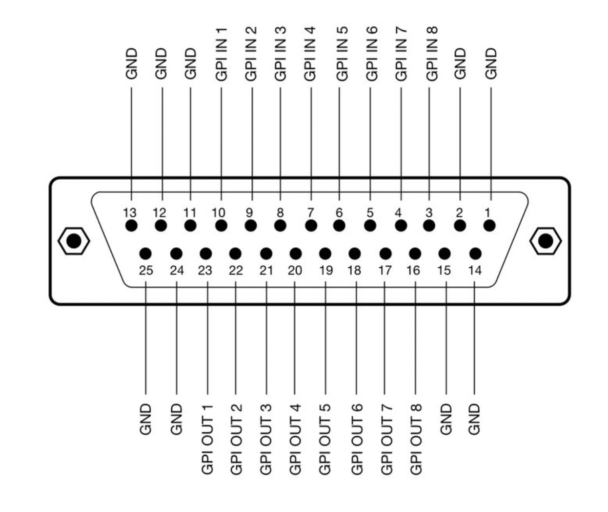
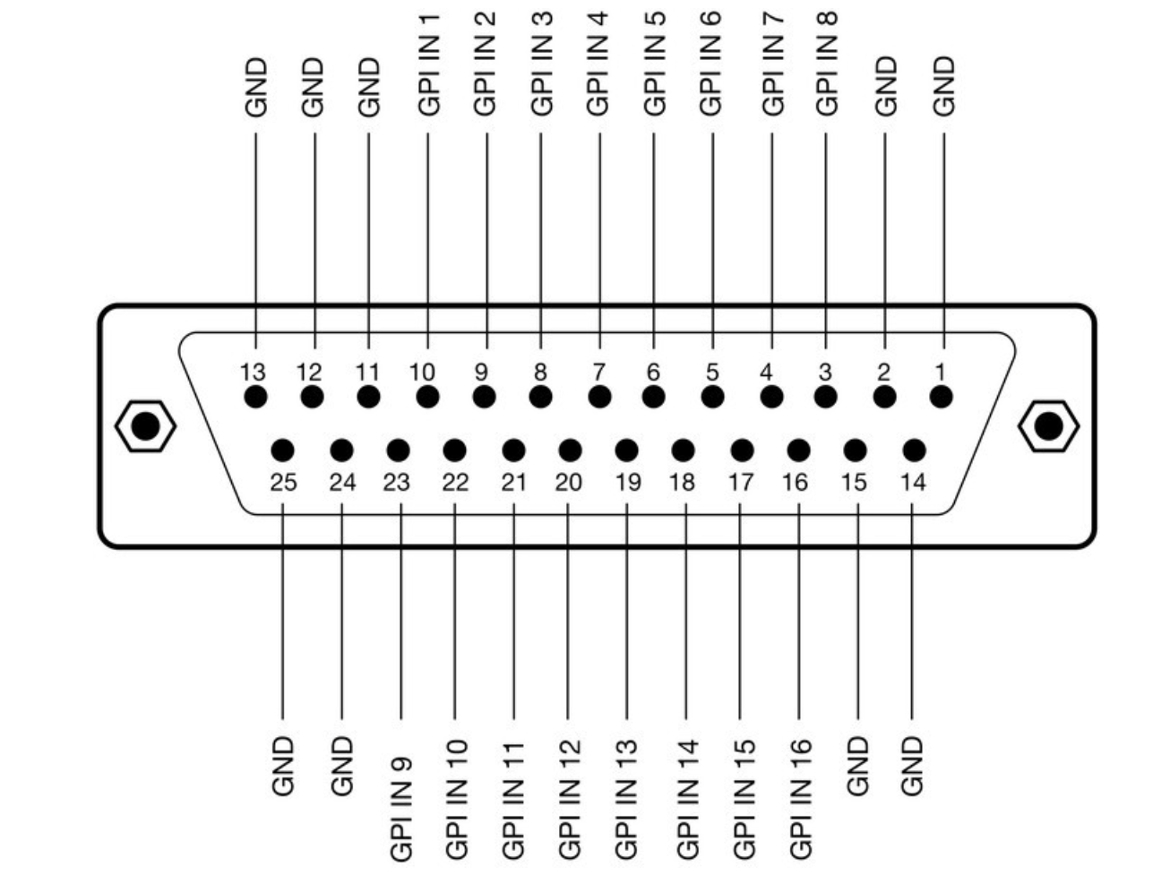
**[](https://wiki.skaarhoj.com/uploads/images/gallery/2022-10/sdi.png)**The Blackmagic 3G-SDI Arduino Shield supports the following formats using SDI Level B: 720p50, 720p59.94, 720p60, 1080i50, 1080i59.94, 1080i60, 1080p23.98, 1080p24, 1080p25, 1080p29.97, 1080p30, 1080p50 (output only), 1080p59.94 (output only) and 1080p60 (output only), but the camera does not have to be running the same video format as the program input, so you can use cameras in Ultra HD while the camera protocol is sent over HD signal to the camera. #### **Eth-GPI Link and Color Fly DB-25 Connector**The Eth-GPI Link and Color Fly have 8x GPI Inputs and 8x GPI Outputs, this is different than the SDI-GPI Link.
**[](https://wiki.skaarhoj.com/uploads/images/gallery/2022-10/eth-gpi.png)** #### #### **RCP v2 DB-9 Connector**The RCPv2 only has 1x GPI Input that is programmable, this is different than the RCP Pro.
**[](https://wiki.skaarhoj.com/uploads/images/gallery/2022-10/db-9-rcpv2.png)** #### #### **SDI-GPI Link DB-25 Connector**The SDI-GPI Link has 16x GPI Inputs and 0x GPI Outputs, this is different than the Eth-GPI Link.
**[](https://wiki.skaarhoj.com/uploads/images/gallery/2022-10/sdi-gpi.png)** #### #### **Tally Box and Lights** The pinout of the RJ-45 connector is as follows: 1\. GND 2\. 12V 3\. 5V control signal for red tally 1 4\. 5V control signal for green tally 1 The next four are for daisy-chaining tally lamps: 5\. 5V control signal for red tally 2 6\. 5V control signal for green tally 2 7\. 5V control signal for red tally 3 8\. 5V control signal for green tally 3 Our tally lamps need 12V power in order to light up the LEDs. The control signals are 5V so whenever you apply 5V on one of the pins the corresponding LEDs will illuminate. **[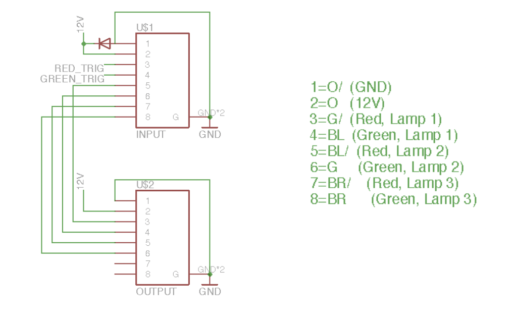](https://wiki.skaarhoj.com/uploads/images/gallery/2022-10/tally-box.png)** # UniSketch Panel Hardware Calibration This guide is for doing hardware calibration on analog hardware components of UniSketch panels that are integrated into a Blue Pill workflow. For information on hardware calibration on analog hardware components of Blue Pill inside panels please see: [https://wiki.skaarhoj.com/books/blue-pill-reactor/page/hardware-calibrator](https://wiki.skaarhoj.com/books/blue-pill-reactor/page/hardware-calibrator) For the analog calibration the Skaarhoj Firmware Updater application is needed. It can be downloaded here: [https://www.skaarhoj.com/legacy-downloads](https://www.skaarhoj.com/legacy-downloads)UniSketch Analog Hardware Component calibrations are stored in the panels EEPROM and are used when controlled by a Blue Pill panel.
1\. Connect the UniSketch panel to the computer via the Micro USB port on the port side of the panel. 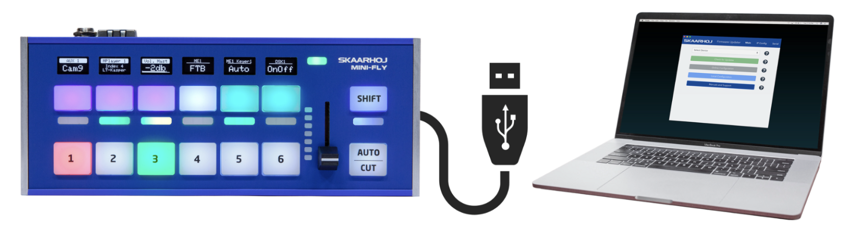 2\. Open the Firmware Updater Application. 3\. Select the device in the port section of the updater. 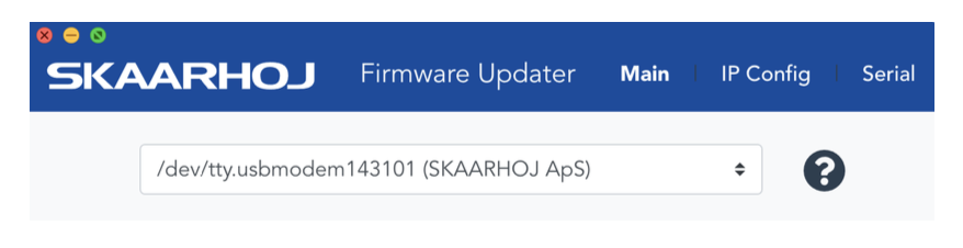4. Click over to the Serial Monitor tab. #### **PTZ Joystick** To see the values of the PTZ joystick deadzone use the command: **“show joystickDeadzone”** Shows joystick deadzone values *if* they have been set via “joystickDeadzone=X,Y,Z” To set the values of the PTZ joystick deadzone use the command: **“joystickDeadzone=X,Y,Z”** Set deadzone values for a joystick component X = Pan deadzone in percentage Y = Tilt deadzone in percentage Z = Zoom deadzone in percentage Default values are 20%. Applicable values are between 1% and 100% Example: “joystickDeadzone=5,10,20” equals 5% pan, 10% tilt and 20% zoom deadzone #### **RCP Joystick**Serial monitor commands can be use with non motorized faders and t-bars but were designed for the RCP Joystick.
To see the available analog components available: **”list analog”** Lists analog hardware components on the controller with number, description and three calibration values (start/end/tolerance) To show the current analog calibration values: **“show analog X”** Shows readings from analog component X where X is the number given by “list analog”. The readings indicate the value and noise level for the read out. This is useful for debugging. If you move the analog component you should see values change. To hide the analog values: **“hide analog”** Stops the display of “show analog” To calibrate the analog component: **“calibrate analog X”** Starts calibration of analog component X. Instructions will be posted in the serial monitor. The steps involve moving the analog component to various positions. When instructed to move the joystick to the end point (all the way up or all the way down, it does not matter which) then in the serial monitor type ok. Continue to follow the instructions as prompted. To reset the calibration to defaults: **“clear analog X”** Resets calibration data for analog component X to default. If X is not given it resets calibration data for all components. To force calibration values: **“set analog X=start,end,tolerance”** Forces calibration data “start”, “end”, and “tolerance” for component X. This is best used when needing to up the tolerance.For full list of available serial monitor commands for UniSketch panels, see page 23 of the UniSketch Installation and Operations manual here: [https://github.com/SKAARHOJ/Support/blob/master/Manuals/SKAARHOJ/SKAARHOJ\_Manual.pdf](https://github.com/SKAARHOJ/Support/blob/master/Manuals/SKAARHOJ/SKAARHOJ_Manual.pdf)