Parts of Reactor
A breakdown of the different sections and elements within Reactor
Projects
Projects are the unit that have a title, description and references to a panel collection, a device collection, and a configuration. This design provides the flexibility to use the same set of SKAARHOJ panels but quickly change to another location of devices with other IP addresses for example. Or keep the same devices and panels, but run a different configuration serving a different user group of operators.
When a Blue Pill ships it has a default configuration is as below. It is set in simple view with only the basic information available.

Over time a project collection could look like below, with different projects sharing some files like device collection, panel collection, or configurations.
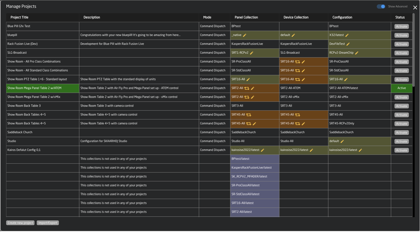
Unlike UniSketch where a change of configuration and device cores needed an online connection to SKAARHOJ server, on Blue Pill everything is stored locally in Reactor. Only software upgrades or installations of non-existing device cores and applications need communication with the server.
Creating Projects
To create a new project click Manage Project within Reactor Home.

Select Create new project on the projects pop up.

There are two main parts of the project: Name and Description.

| Name | Customizable project name |
| Description | Option description of the project for reference |
Click Create to automatically go into the newly created blank project.
Import Projects
It is possible to import to more easily share between different Blue Pill devices. This option is available next to create new projects in the Manage Projects pop up.

Import allows for a simple file upload. With the option to have the file name become the project name.

Editing Projects
To change the details of the project click the project name within Reactor Home

Or within any of the project detail boxes on the projects pop up.

It is then possible to customize the name and description of the project. Press Save.

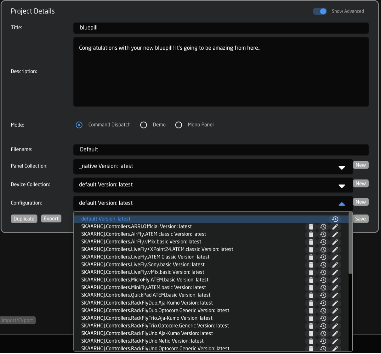
Enabling Advanced view brings about extra options for editing the project outside of the basic details.

| Mode | 1. Normal for normal operation 2. Devices only for when a Blue Pill will only be used to run device cores and not panels |
| File Name | Master name for the file when making new collection, configuration, and exports |
| Panel Collection | Allows for the sharing of panel collections across projects on a Blue Pill device. |
| Device Collection | Allows for the sharing of devices collections across projects on a Blue Pill device. |
| Configuration | Allows for the selection of a specific layer files in the configuration across projects on a Blue Pill device |
| Duplicate | Duplicates the projects |
| Delete | Deletes the project |
| Save | Saves changes to the project details |
| New | Creates a new panel collection, device collection, or configuration file for the project.
|

Layer Configuration Version Look Up
In the layer configuration section, it is possible to access autosaved versions of the configurations. This is useful when a lot of changes have been made and it is necessary to roll things back a little.
When in the Configuration section, click on the little clock symbol next to the layer to see previous versions.
Available versions are: every change from the last 24 hours and as 1 file per day for 10 days.
It is also possible to add tags or comments to individual versions. When a tag or comment is added to the version, it will no longer be deleted based on the default time scale and will persist.

Panels
The Panels section is where new SKAARHOJ panels are added to the panel collection of the project. By default the Blue Pill or Blue Pill Inside panel will already be in the Panels section.

There are two ways a panel can be added, Auto Discover and Manually.
For compatibility with Blue Pill, a UniSketch panel needs to be running UniSketch v2.5.14 or later. Starting with UniSketch v2.5.18, there were changes made to the Raw Panel implementation which is used to connect to the Blue Pill. These changes allow for better hardware mapping inside Blue Pill.
Please make sure your UniSketch panel is running the latest UniSketch release version using the Firmware Updater Application.
Auto Discover
Panels can easily be discovered by mDNS look ups on the same subnet the Blue Pill is on. This makes it very easy to discover and include a panel in the configuration. mDNS will usually search the current subnet, but with a correctly configured Blue Pill, panels on other subnets can easily be included too as long as the IP and port is known to the user.
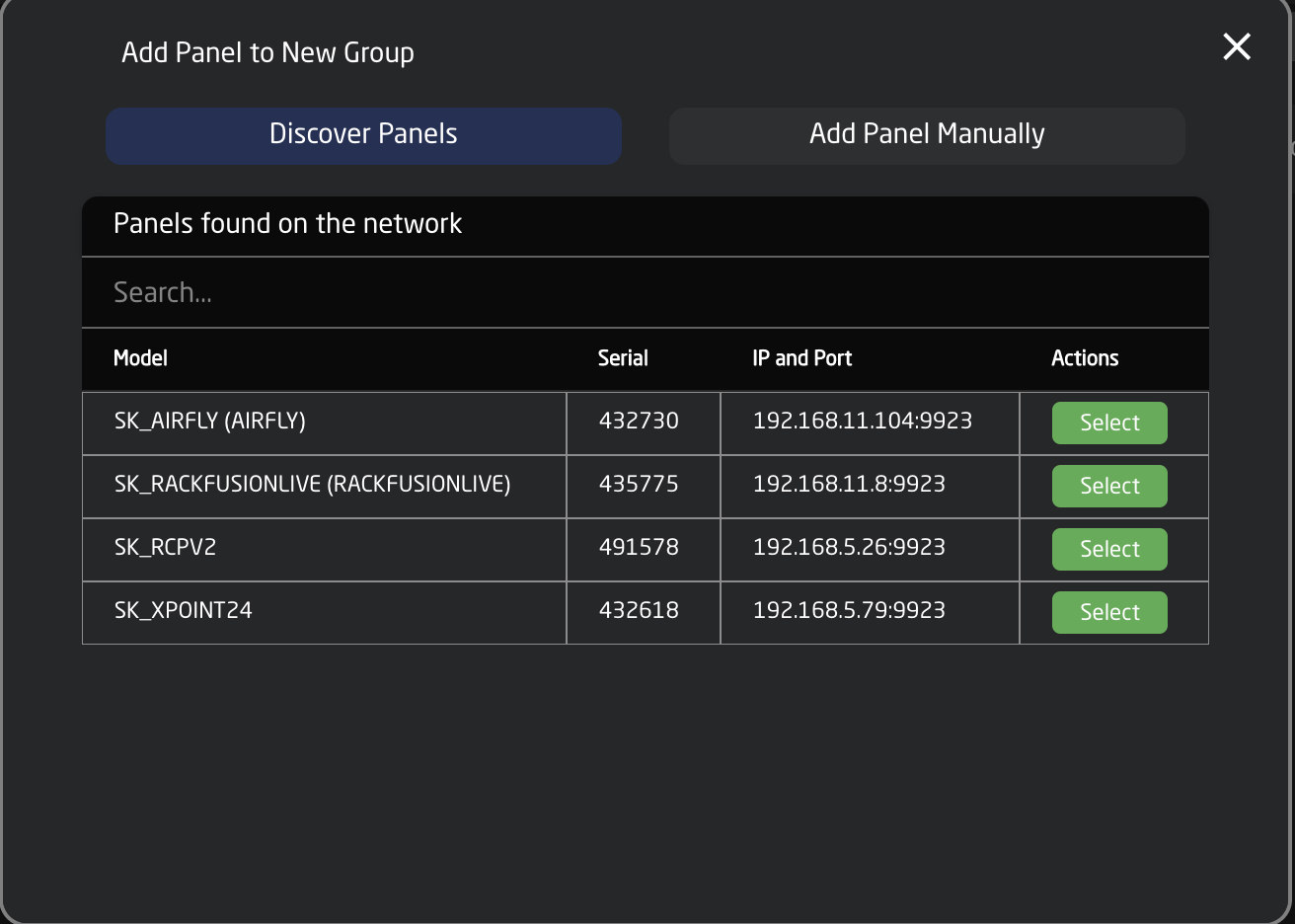
Pressing SHIFT + the green Select button will allow for multiple panel selection.
Manually Added
Panels can be picked from SKAARHOJs included library of products. Following a manual choice of panel, the user will have to enter the IP address himself including any constraints desired. See the Panel Details section for set up.

Pressing SHIFT + the green Select button will allow for multiple panel selection.
Unknown Skaarhoj Panel
Some legacy model UniSketch panels have not yet been added into our manual panel selection. These panels can still be added manually by selecting Enter Details Manually option in the Manually Added panels section.
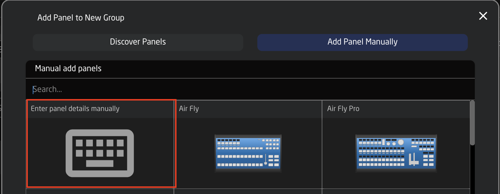
This will bring up the option to add the IP address and communication port for the Blue Pill device to connect to.

Panel Details
The immediate view of a panel in the Home Screen show its name, connectivity status, mapping, and any available constant sets. There is also a small light bulb button for lighting up the panel for quick real world identification.
Clicking on the panel name will open up the details. Here the general information about the panel, the settings, and the constraints can be seen and adjusted. By default the controller name will be the same as the model name, the ID will be auto generated in order, panels will per default be in the main group and the status will be active. A controller’s status needs to be active for use.
Constraints are requirements regarding the panel. Here it is determined which models are allowed, which serials are allowed, which IP and port numbers can be used and if the panel is of the server or client type (Raw Panel protocol related). Empty constraint will allow any value, but consider that a configuration always maps functionality to hardware component IDs which will change with the panel model for obvious reasons, so it’s rarely a good idea to omit constraints such as the allowed models.
By default our controllers connect using port 9923. It is important to include the port number, separated from the IP address by a colon (:), for example 192.168.11.124:9923
From inside the panel details it is also possible to delete the panel, simulate the panel if it is not immediate available for testing, ping the panel, and adjust some general controller settings.

Panel Simulate
The Panel Simulate option available in the panel details allows for an interactive simulation of the panel’s behaviors based on the configuration/mapping and devices without needing the physical panel available. Pressing Simulate will immediate relocate to the Simulator page for this panel, it is best to wait on simulating a panel until mapping has been selected and devices added.

Panel Groups
Multiple panels can be arranged in groups. This allows for an easy visual breakdown of controller set ups. To access the information, set the Home screen to show panels by opening the settings menus in the lower right corner of the packages page.

In the settings pop up, enable Panel Groups.

Enter the panel group set up by click the panel group name above the panel details.

Inside the group details it is possible to edit the group name, view the group as a table, or in an adjustable graphical view. Which group a specific panel is in can be set in the Panel Details, by default all panels start in the Main Group.
In Table view the basic information of the set up is given including the panel name, id, status, serial number, model, IP, Port, connection type, and change the default display settings for the group.

Confirm Panel Connection
A panel that has established a connection with a blue pill will no longer display “Waiting for Blue Pill” or “Waiting for Raw Panel”.
Devices
The Devices section is where new devices are added to be connected with the SKAARHOJ panels. There are two ways a device can be added, Auto Discover and Manually.
Auto Discover
Searching on the network for devices will find many types by a combination of mDNS look-ups and other methods. However, not all devices can be discovered easily, but with those that can, it’s a simple click of a button to add it to the Blue Pill device collection. Following an Auto Discover some device details may still be needed to establish connectivity. See Device Details section for set up.
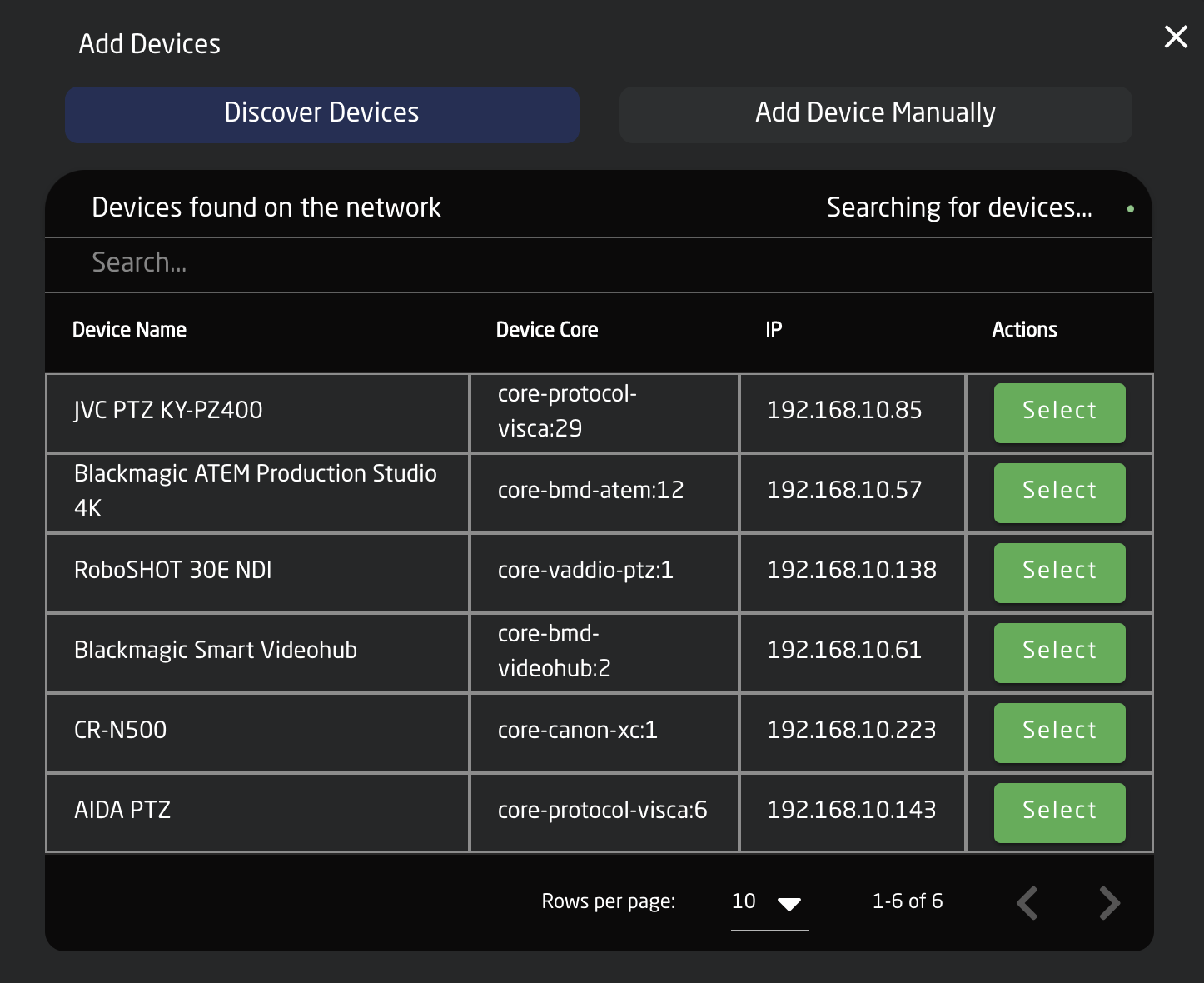
Pressing SHIFT + the green Select button will allow for multiple device selection.
Manually Added
If a device must be added manually, it’s easy to look it up in the list of supported models. Following a manual choice of device, the user will have to enter the IP address and other possible device detail information. See the Device Details section for set up.
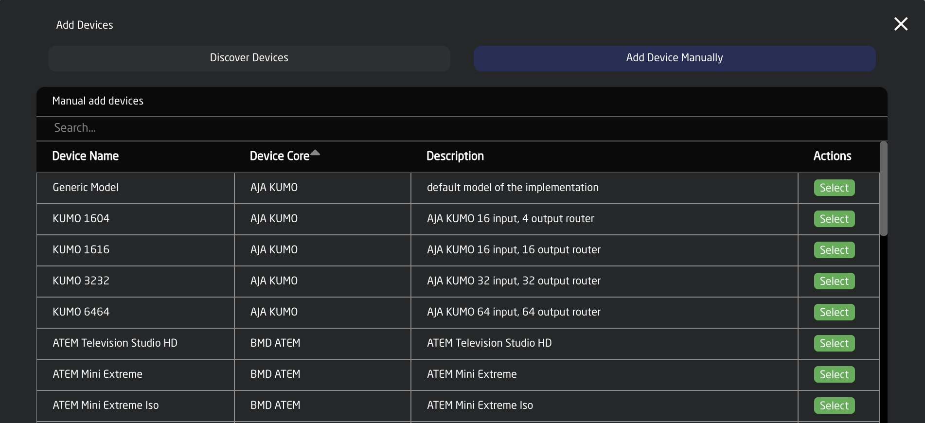
Pressing SHIFT + the green Add Device button will allow for multiple device selection.
Adding Based on Core
When the Home screen is in Advanced mode, it becomes possible to add device pre-filtered based on the device core. Both methods of adding the device (discovered and manually) are still available.

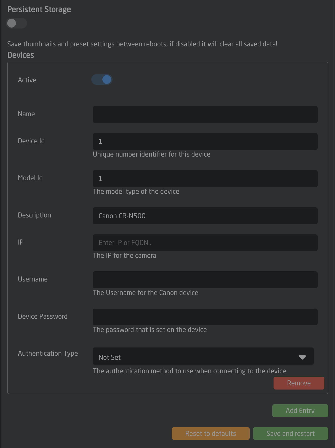
Device Details
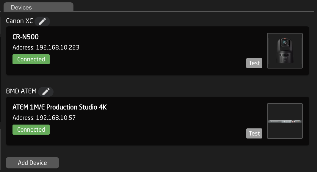
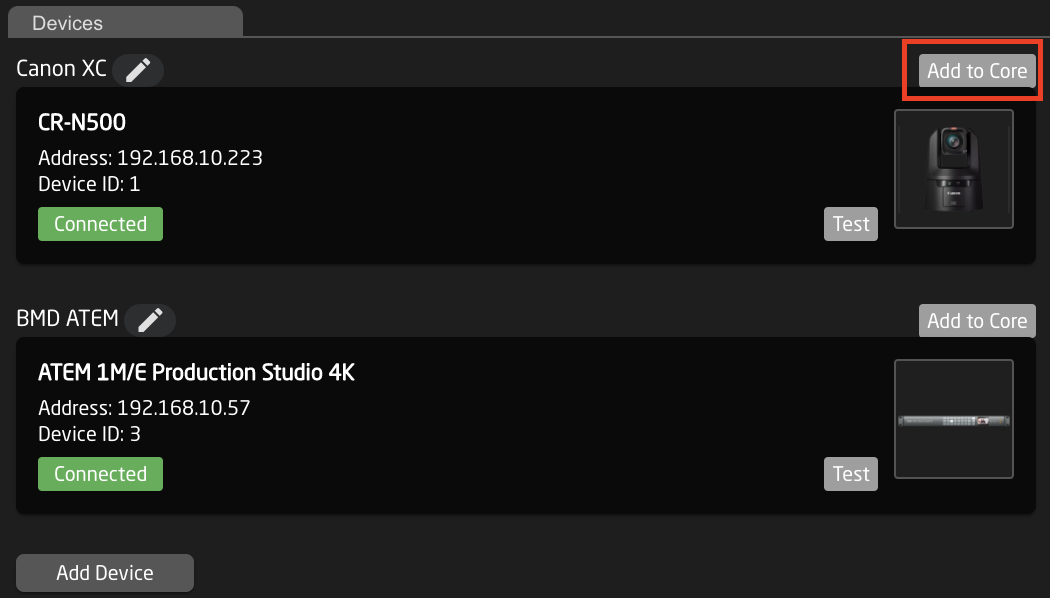
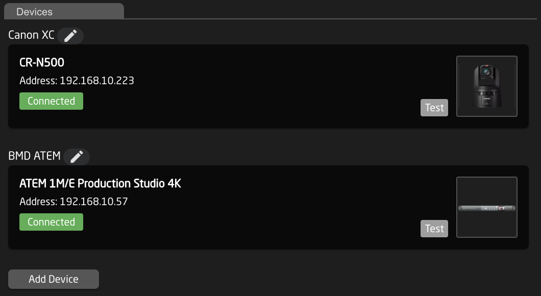
Devices are presented in a nice overview with their connectivity status and IP address shown clearly.
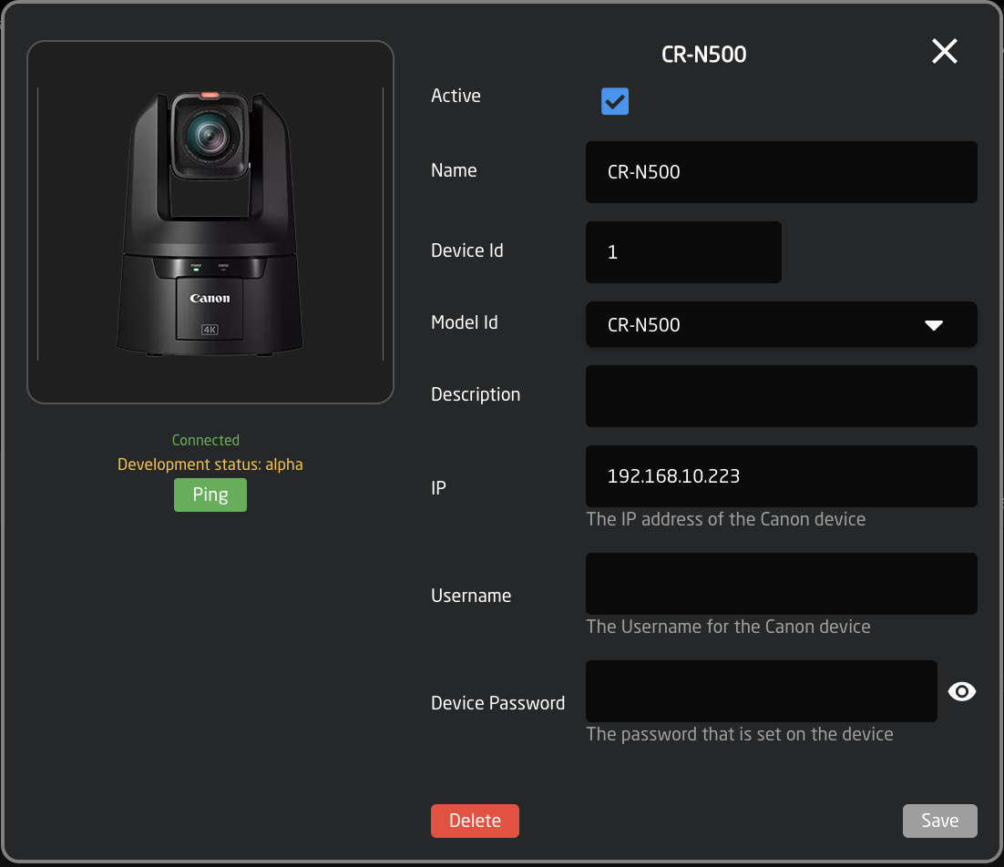
Clicking on a device’s name in the Devices section will open up the details. Here the active status, IP address, Username and Password, Device Name, DeviceID, ModelID, and Description can be adjusted. (Details shown here are for a Canon CR-N500 PTZ camera, available detail options are device specific) . The device name and description are customizable. The device name will be the default name used by any camera selector for a display name. The status must be Active to control the device. The Ping button will open the ping tool to check the connectivity, stability, and latency on the connection to the device.
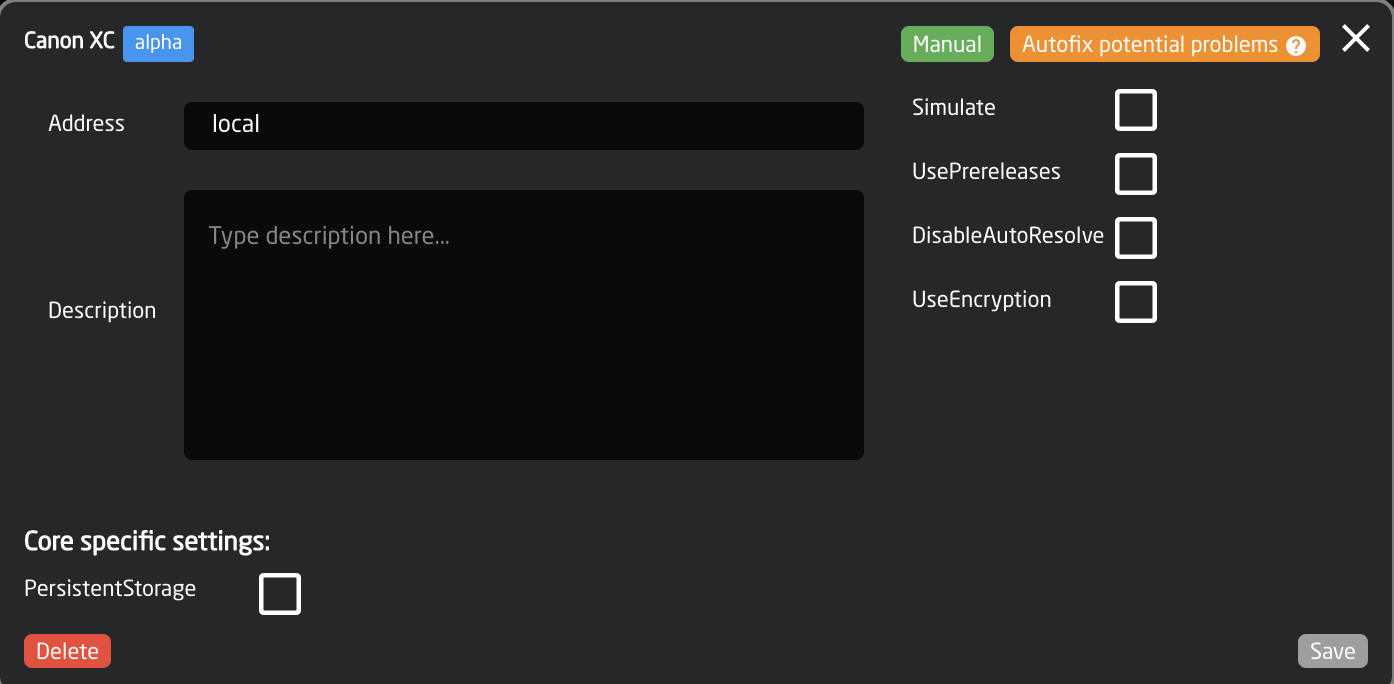
Device Core Details
Devices will be shown broken down into different groups based on their associated device core. Device cores are auto loaded onto the blue pill when a new core is selected via a device.
Clicking on the Device core name associated with the devices will open additional details.
|
Name |
Description |
|
Maturity Level |
Development maturity level of the device core. See Packages section for more information on the different levels. |
|
Manual |
Opens device core manual to see controllable parameter list. |
|
Auto-fix Potential Problems |
Re-syncs device core locally. |
|
Address |
The location of the device core. Local references the core on the individual Blue Pill. To connect to the core running off of a remote Blue Pill, use the IP address of the remote Blue Pill (must be accessible from local subnet). |
|
Description |
Custom description for personal reference. |
|
Delete |
Deletes all devices using the core but not the core itself. |
|
Simulate |
Runs the device cores in simulation mode to see how it would work on the controller. The individual devices needs to be ‘active’ for it to simulate. |
|
UsePrereleases |
Uses the prerelease versions of the device core. |
|
Disable AutoResolve |
coming soon |
|
Use Encryption |
coming soon |
|
Core specific settings |
Settings specific to the individual device cores. Mouse over the name in the web interface for more details. |
Mapping
The Mapping section is built into the Panels section and is designed to provide a view into the current configuration and often it will refer to embedded standard configuration with associated constant sets for setting up cameras, router input/outputs or switcher inputs.
Configuration
The drop down allows you select from the default configurations Skaarhoj has made for the specific panel type and from your user generated configurations, create custom configurations, or remove configurations. Most often the needed default camera control configuration will be the Generic Control configuration. This one is designed to be the most flexible for adding multiple brands of cameras with extreme ease.
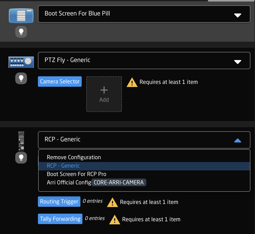
User generated or modified configurations will displays with an orange CUSTOMIZED label next to it. 
Constant Sets
The final step is to fill in any setup tables, also known as constant sets. The constant sets are available based on the chosen configuration and should contain entries such as specific cameras for a PTZ controller, or the inputs for a video switcher etc. They are most common when working with PTZ cameras and routing panels, though may be available for additional device configurations. A detailed breakdown of using available constant sets tables can be found on our wiki page: https://wiki.skaarhoj.com/books/blue-pill-reactor/chapter/understanding-constant-sets
The setup tables will auto save and quickly appear on displays and enable the function.
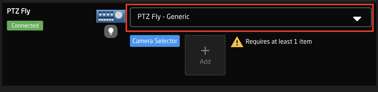
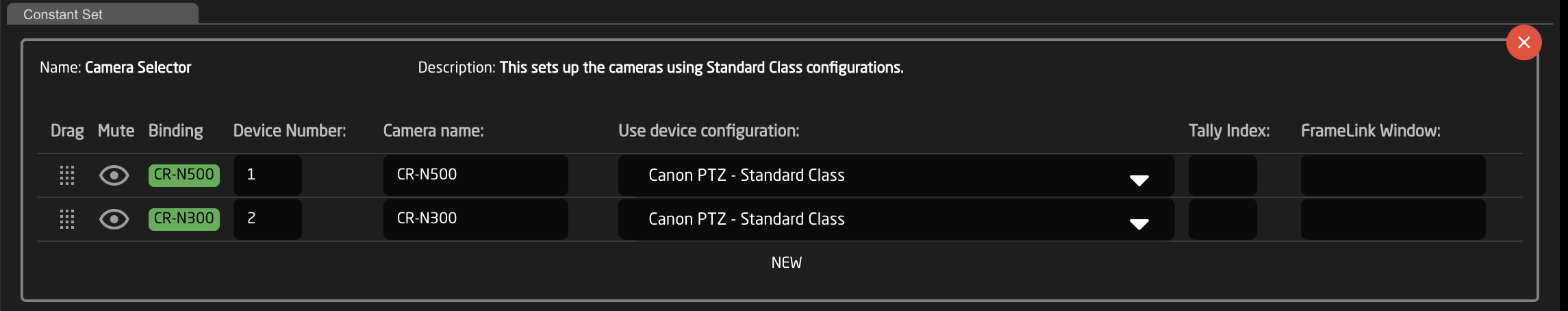
An example of a setup table would be a camera selector and can be seen below. These can be different depending on the selected configuration. From here the order on the camera selector row of the panel will be set as well as the desired name on the displays.
There are a couple of ways to work with the camera selector.
In the Panels Section, it is possible to click the ADD button next to the Camera Selector to select a device already in the device collection in the devices section or to add a new discovered or manually added device. Adding one with Discovered or Manually will require additional information added in the Devices section. Using a device from the current Device Collection will auto populate the Camera Selector, though it is still smart to click into the selector to double check the information is correct.
It is possible in the click and drag the camera icons in the Panels section to rearrange the camera selector row on your panel. The order that is seen in the home screen will be the order on the panel.
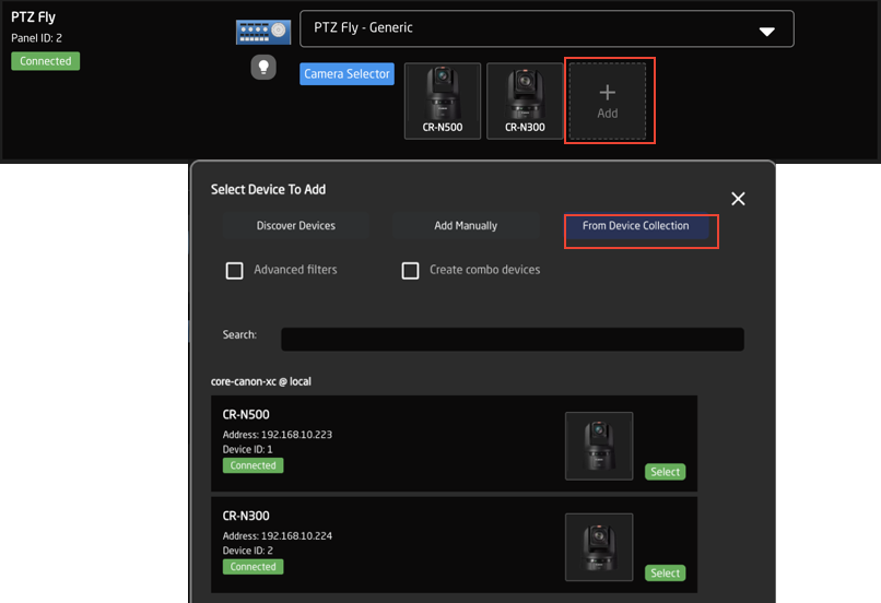
Clicking on the Camera Selector button will open the camera selector’s Constant Set box. In there are a variety of options, some of which are not available in the Panels section. These options are device and configuration specific so may vary.
|
Column |
Description |
|
Drag |
Allows for quick rearranging of camera order. Right clicking on drag will allow for deleting the row. |
|
Mute |
Allows for removing access to a specific camera or to leave a blank spot on the panel |
|
Binding |
Allows for the selecting of a specific connected camera |
|
Camera Name |
Customizable name to appear on the displays. Character limit is determined by size of display and can vary. |
|
Device Number |
Ties the camera selector to the specific device. This is found in the Devices section. Each device will have a unique device number per device core. This box should auto-populate when a camera is selected in binding |
|
Link Selector |
Selects the protocol based configuration associated with camera. Needed protocol can be seen in the Devices section, each device is grouped into their native protocols. Double check the correct configuration is selected. Improper selection will effect camera control. |
|
Channel Link |
Selects the needed protocol for Iris/Master Black control. For cameras without a variable lens this will follow the same protocol as the device. For cameras with a variable lens, select the protocol for the attached lens. Not available on all configuration classes. |
|
Tally Index |
Sets the Tally Index number to connect with associated tally source device. See Blue Pill/Reactor Manual for more information. This column does not need to be filled out for standard operation. |
|
Route Index |
Sets the Route Index number to connect with associated routing device. See Blue Pill/Reactor Manual for more information. This column does not need to be filled out for standard operation. |
|
FrameLink Window |
Sets the FrameLink Window value associated with the FrameLink device core for use with FrameLink compatible devices. See Blue Pill/Reactor Manual for more information. This column does not need to be filled out for standard operation. |
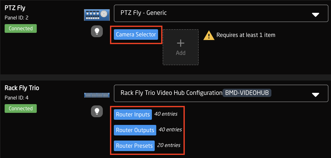
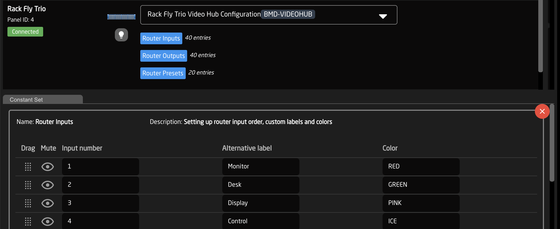
An example of a router inputs selector can be seen below. These can be different depending on the selected configuration and device. From here the order on the inputs/outputs row of the panel will be set as well as the desired name on the displays and button color.
|
Column |
Description |
|
Drag |
Allows for quick rearranging of input/output order on the panel. |
|
Mute |
Allows for removing access to a specific input/output or to leave a blank spot on the panel. |
|
Output Number/Input Number |
Ties the selector to the specific input/output of the controlled device. This is determined by the individual router. |
|
Alternative Label |
Customizable name to appear on the displays. Character limit is determined by size of display and can vary. |
|
Color |
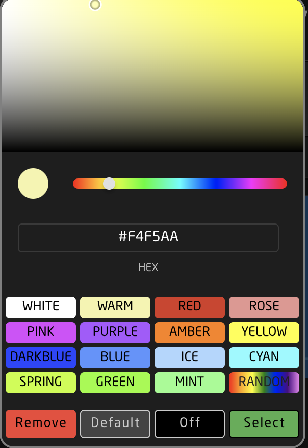
Sets the button feedback color. Color options are: OFF, WHITE, WARM, RED, ROSE, PINK, PURPLE, AMBER, YELLOW, DARKBLUE, BLUE, ICE, CYAN, SPRING, GREEN, MINT. |
Configuration
Please Note: This page is about the configuration page but is not a guide on how to make an advanced configuration. For guides on making configurations please check out: https://wiki.skaarhoj.com/books/blue-pill-reactor/chapter/advanced-configuration
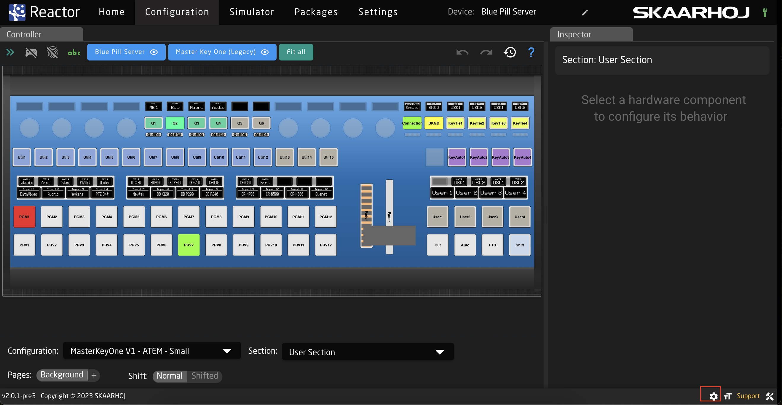
The Configuration page is described how it appears starting with Reactor v2.0.
For a more customized configuration either self constructed or to modify a default configuration used in the Mapping section it is necessary to move off of the Home page and into the Configuration page.
There are three main parts of the Configuration page, however only two of them are directly presented, Controller section for an overall view of the panels and the Inspector where parameters and behaviors are assigned to the hardware components. The third, more advanced section, is the Tree view (not pictured) where you can see the whole mapping of the configuration and gives more advanced ways to configure the panel.
Controller
The Controller sections is full of many tools to allow for navigating through the configuration and even using a fully functional simulated version of the panels.
Please note, this section may act or look different when the Tree section is open.

Starting at the top of the page, there are a few different ways to interact with the interface.

| Arrows Icon | Toggles open/close the Tree View. (see Tree section for more information) |
| Controller Icon | Toggles on/off simulation mode. When on, the graphical view of the panels acts as a real panel. When simulation mode is not on, it is in configuration mode. |
| Fingerprint Icon | Toggles on/off listening mode. When on, interacting with a physical hardware component on the Skaarhoj panel will open that component in the Inspector. |
| ABC Icon | Toggles on/off the text labels in the graphical view of the panels. |
| Panel Names | Centers graphical view on selected panel. |
| Eye Icon | Toggles on/off the view of the specific panel in the graphical view. Button turns grey when panel is not visible. |
| Fit All | Positions graphical view to show all visible panels. |

| Back Arrow Icon | Undoes the last change made in the Inspector |
| Forward Arrow Icon | Redoes the last change made in Inspector |
| History Icon | Opens the History View. See History View page for more information. |
| Question Mark | Opens the graphical view movement and color guide. See image below. |
Graphical View Image and Color Guide:
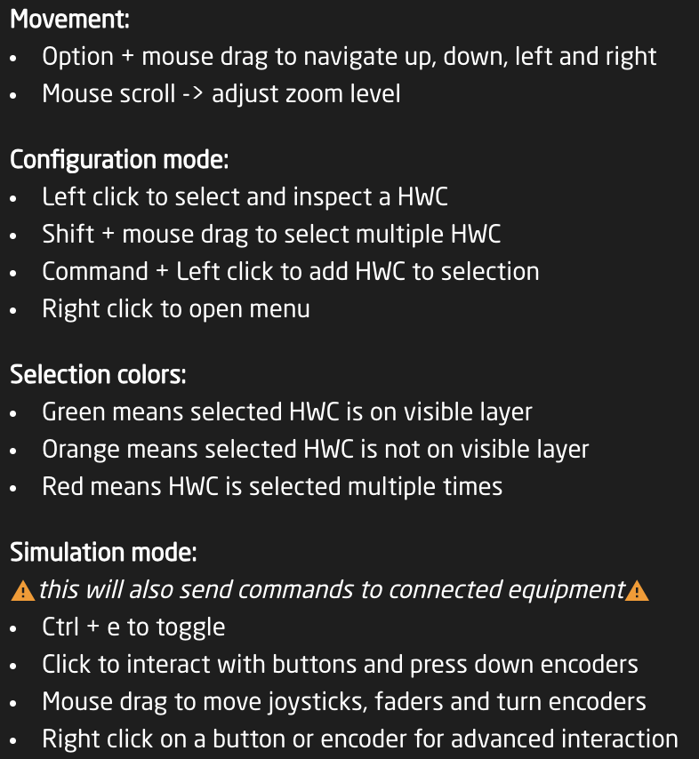
The interactive graphical view displays the panels in the current project in their current state on a grid. The layout of the panels on the grid can be adjusted from the Panel Groups interface accessible on the Home page.
Each hardware component of each panel is selectable from the graphical view to interact with, how that behaves is dependent on which mode you have enabled at the top of the Controller section.
Configuration Mode
In configuration mode clicking on one of the hardware components will open that up in the Inspector to the exact place if that hardware component has been created in the associated section of the selected configuration. If it has not been defined in the section for the configuration it will be greyed out.
Right clicking on a hardware component will open an options menu, even if the component has not been created on the section.

| Create section | Creates a new section in the configuration. |
| Add to section | Adds the hardware component to to the current section. See expanded details below. |
| Remove from section | Removes the hardware component from the current section. |
| Copy | Copies the current configuration of the hardware component to be able to be pasted. |
| Cut | Cuts out the current configuration of the hardware component to be able to be pasted. |
| Paste | Pastes the last copied or cut configuration of a hardware component to the select component. |
| Delete Behavior(s) | Deletes the current behavior or behaviors configured on the component, plus makes it transparent if it is not currently. |
| Clear Contents | Deletes the current behavior or behaviors configured on the component. |
When adding a section a pop up window will be presented where it is possible to define certain details of the section.

| Name | User defined name for the created section. |
| Transparent section | Selecting Transparent section will allow for behaviors configured on a lower layer of the tree for that hardware component to show through. If not transparent, the hardware component will remain blank unless configured. |
| Advanced | Toggles on/off Advanced for the section creation tool. |
| Layer Selection | Allows for the selection of which layer in the tree the section is created on. Available only with Advanced toggled on. See image below. |
| Cancel | Cancels the creation of a new section. |
| Submit | Submits and saves the new section. |
Layer selection filter for the section creation tool, allows for the selection of any layer in the tree for the current project. 
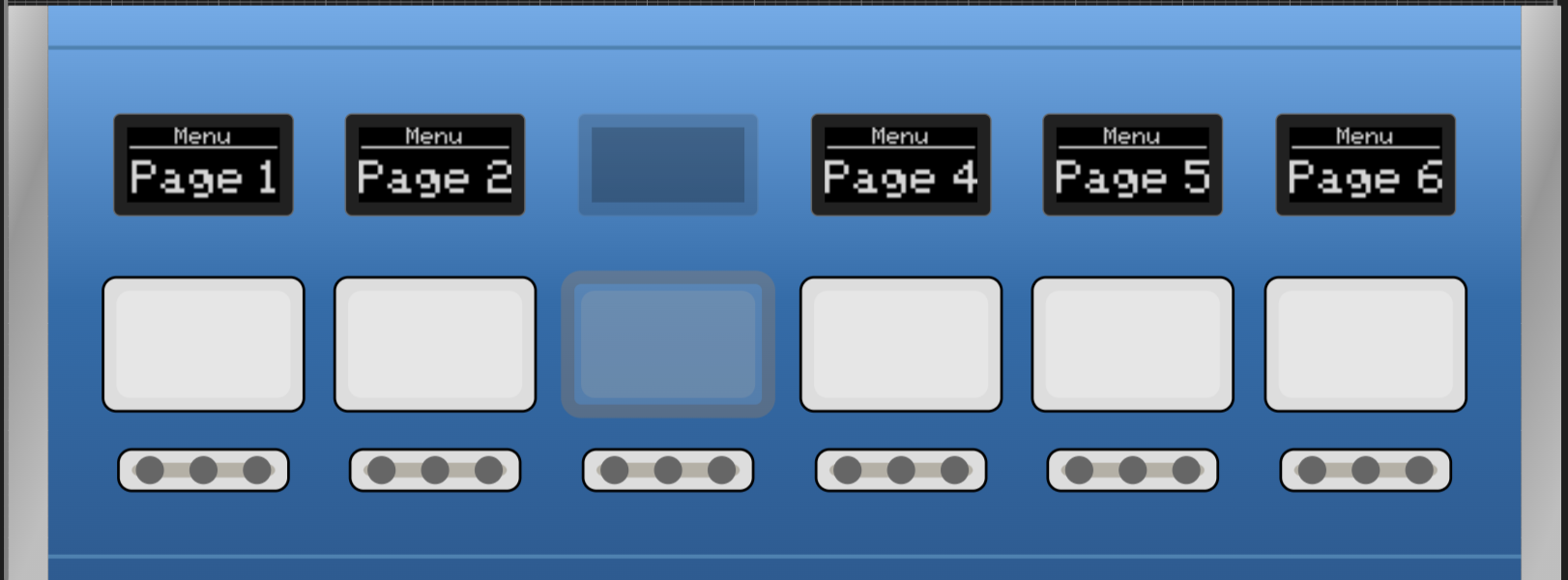
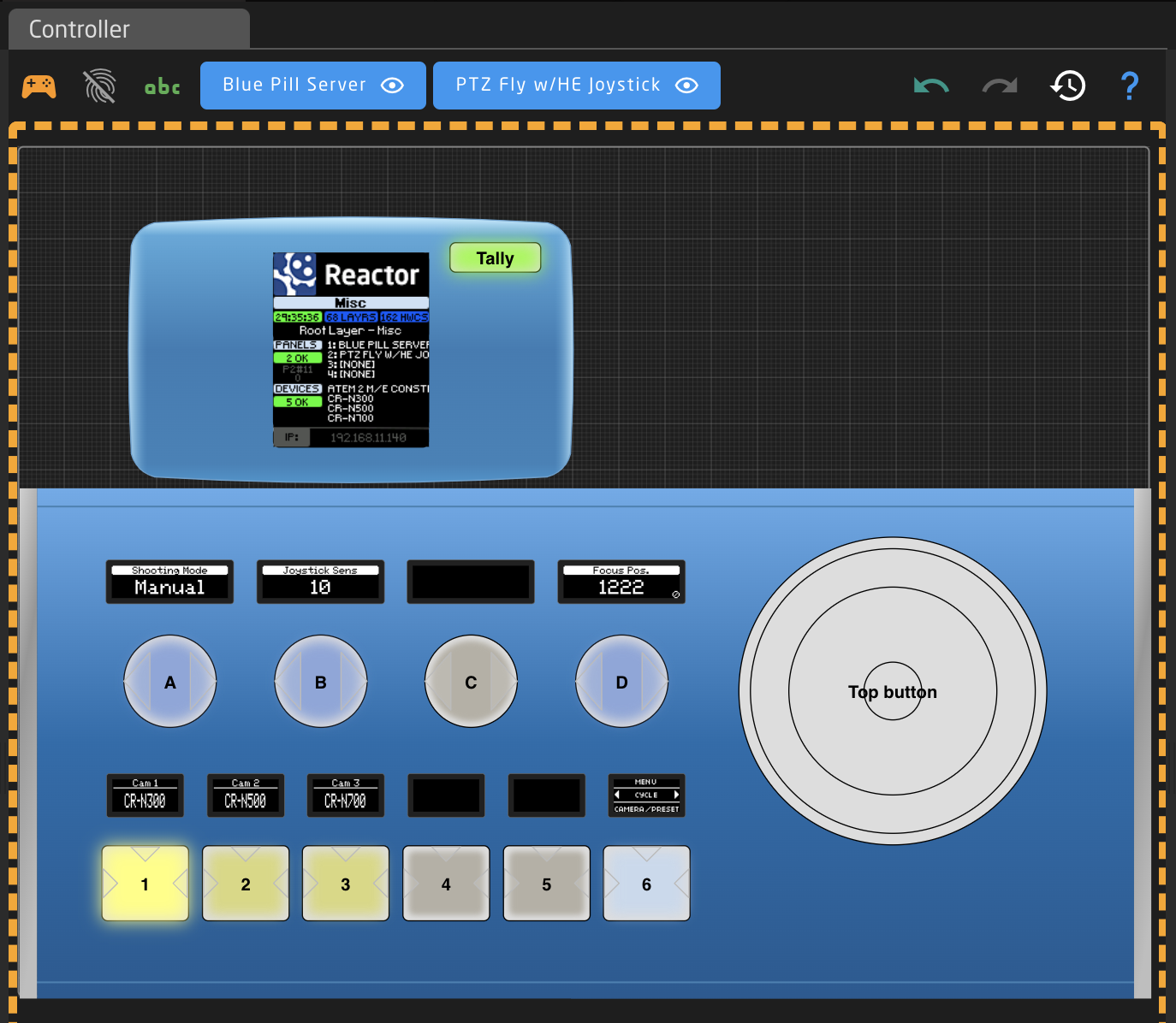
Simulation Mode
In simulation mode, the graphical view works actually controls the panel and all connected devices. In this mode the entire graphical view will have a yellow dotted line around it.

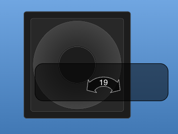
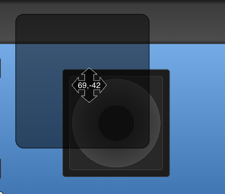
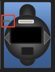
The individual components will also have indicators on them of their use. Below is a selection of hardware components in simulation mode.
| Button | Small triangles represent left, right, top edge presses |
|
| Encoder and Knobs | Triangles represent direction of turn |
|
| PTZ Joystick Twist, Zoom Rocker, XC8 Shuttle Wheel | Arrows represent direction of twist and number is the speed component value |
|
| PTZ Joystick Up/Down | Arrows represent direction of movement and numbers the component value of X,Y axis |
|
| RCP Joystick Up/Down | Line represents the position of the virtual position of the joystick as it is not a motorized hardware component |
|


Right clicking on a hardware component brings up different options then it does when in configuration mode.
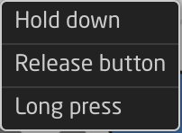
| Hold down | Corresponds to pressing down the button or encoder without releasing it. |
| Release button | Corresponds to releasing the hold down of the button or encoder. |
| Long press | Corresponds to a 1 second long press. |
The bottom section of the Controller section is a navigation tool to move around the configuration of each panel.
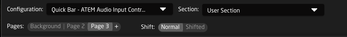
| Configuration | Select between the configuration in the project. The graphical view of the panel associated with the selected configuration will no longer be grayed out. |
|
| Section | Select between the different hardware component sections in the selected configuration. These sections are tied to the configuration, the pages, and the shift levels they were created on. |
|
| Pages | Select between the different page layers of the configuration. Using the + symbol will add more pages. See below for more detail. |
|
| Shift | Select between the different shift layers of the currently selected page. |
|


When creating a new page a pop up prompt will low for the setting of the page name and whether or not the page will be transparent or not. A Transparent page will allow for lower pages or layers in the tree to have their hardware component settings visible or available when on the new page, unless the hardware component is configured on the current layer.
![]()
Right clicking on one of the page will also preset a number of options.

| Copy | Create a duplicate copy of the clicked upon layer. |
| Rename | Rename the clicked upon layer. |
| Disable transparency | Disable the transparency for the clicked upon layer. |
| Delete | Delete the clicked upon layer. |
Inspector
The Inspector is where all the hardware components have their configurations assigned and adjusted. The Inspector section can give a very simple start to getting the configuration going or can be made more complex to create more complex workflows.
Create Behavior
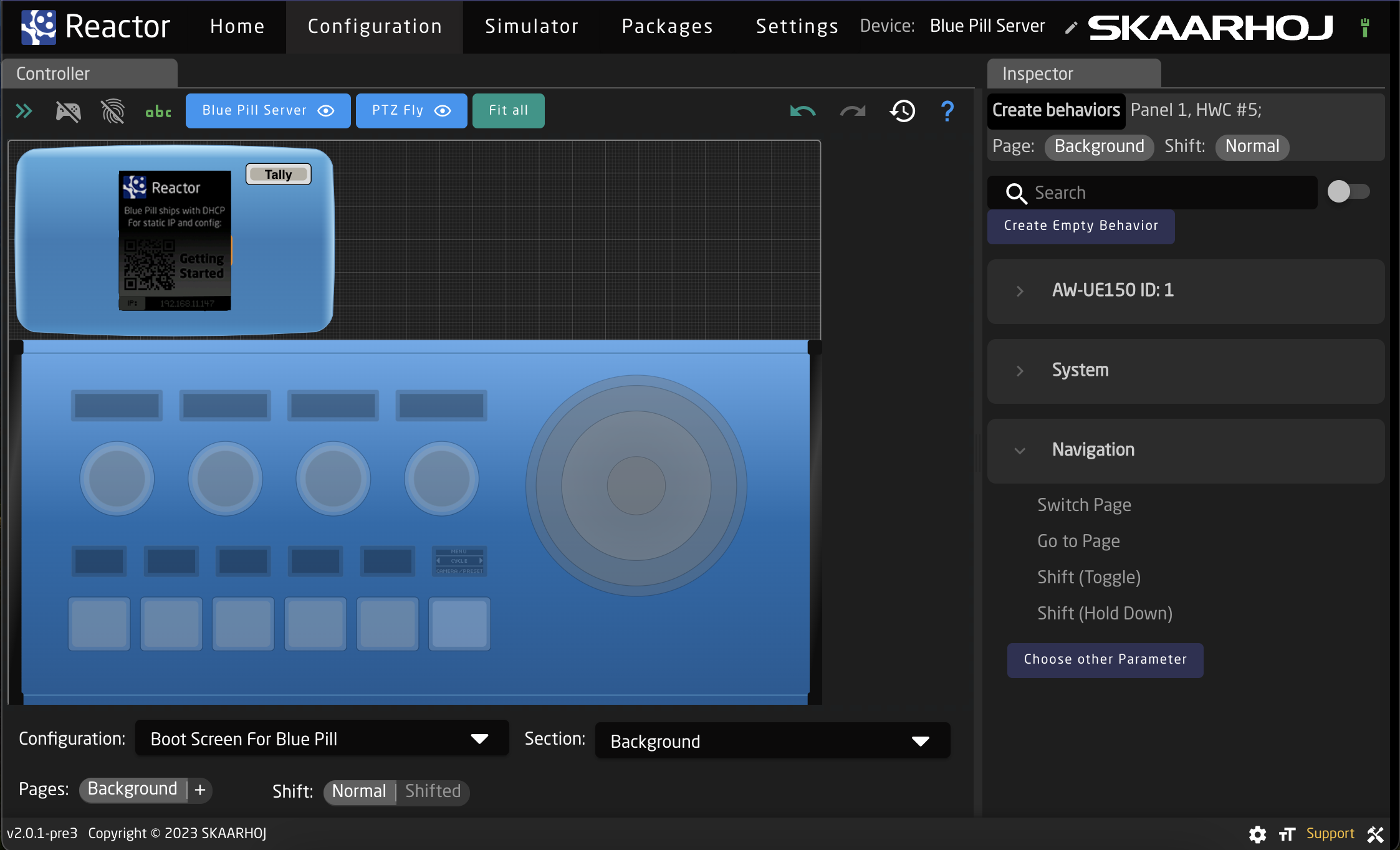
When first configuring a hardware component the Inspector interface the interface will appear as below. This is the Create Behavior Interface. 
Looking at the top of the section:

| Create behaviors | The lighter grey section indicates which specific hardware component is going to be configured, and on which configuration page and shift level it will be on. |
| Search | Search for the specific parameter to configure on the button |
| Device Grouping Toggle | Toggle between seeing Create Behaviors per device or per device core. |
| Create Empty Behavior | Skip Create Behaviors to create an empty behavior to fully configure. |
Below the upper section, the Create Behaviors will be available either per individual device or grouped per device core depending on how the toggle is set. Below the devices have been grouped by their device cores.

Expanding one of the cores, system, or navigation menus the individual parameters become become selectable.

Not every parameter, system setting, or navigation tool is available as a Create Behavior. For those that are not they will need to be self configured. To select an different parameter, select Choose other Parameter.

Full Inspector
Moving in past the simplified Create Behavior interface, the hardware component configurations possibilities become virtually endless in the full inspector. 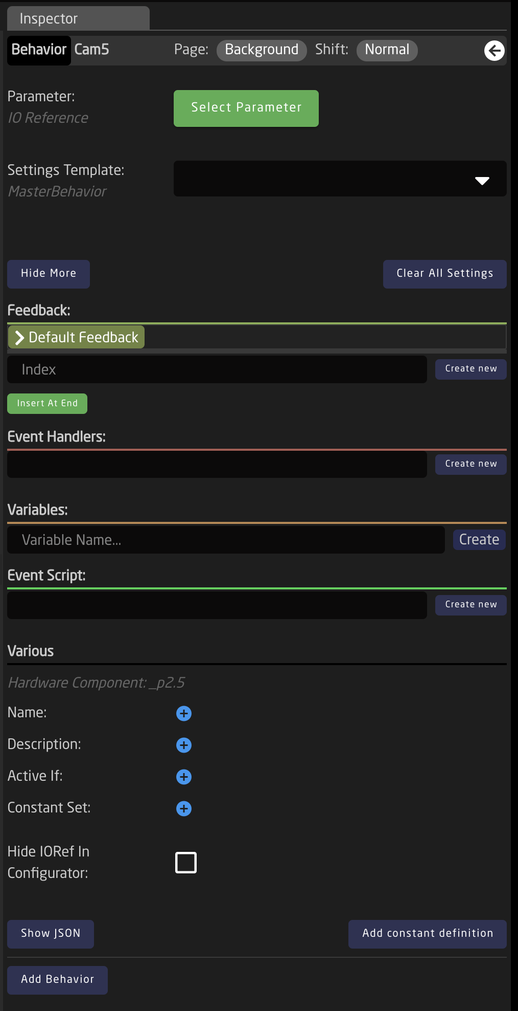
Starting with the top section of the Inspector
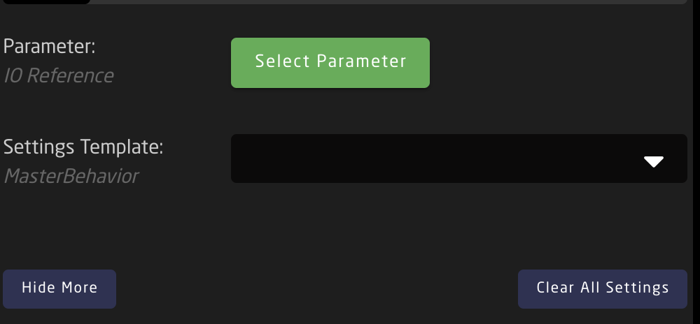
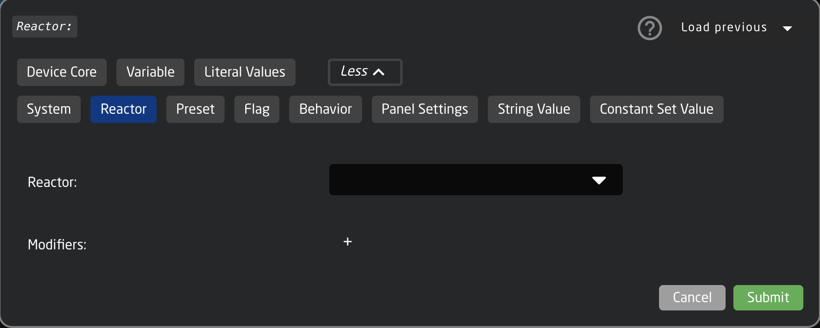
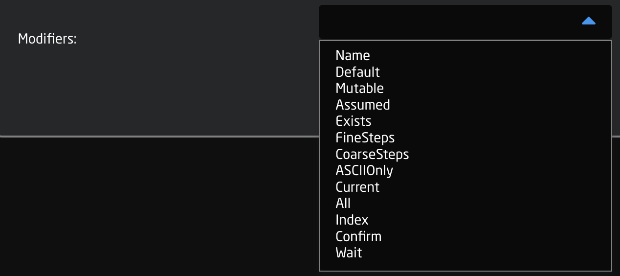
| Parameter | Select what is to be controlled by the hardware component. The parameters have various categories: Device Core, Variable, Literal Values, System, Reactor, Preset, Flag, Behavior, Panel Settings String Value, Constant Set Value; with different further options depending on what is selected.
There is a standard list of available modifiers to add.
There are scenarios where it is not needed to use the Parameter field when configuring a hardware component. |
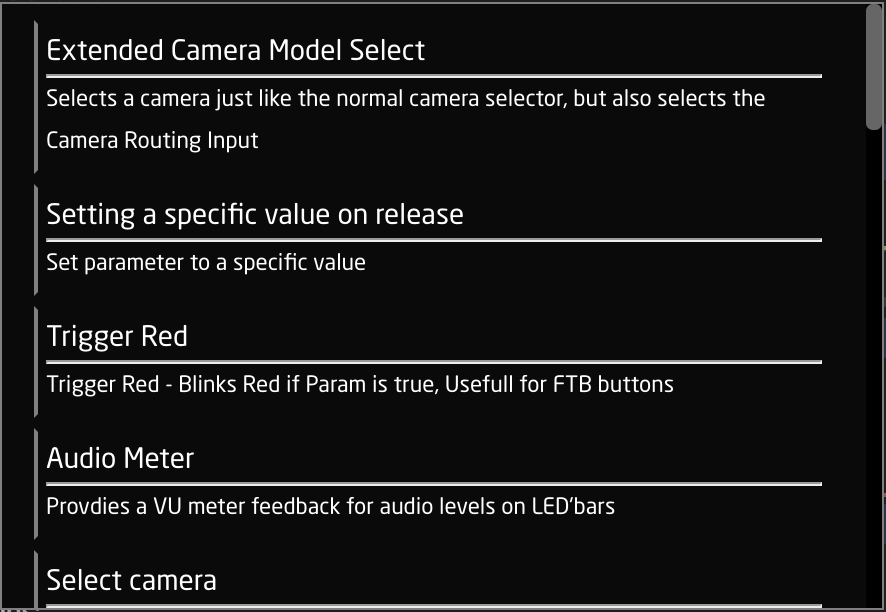
| Settings Template | Predefined templates that can be paired with a parameter for quickly assigning functionality to a hardware component. They can be more generic to work in the same way with various parameters or tailored to specific parameters or device cores. Frequently these are auto selected or suggested when selecting a parameter.
As these are prebuilt templates, they contain information needed for Event Handles and Feedback. There are scenarios where it is not needed to use the Settings Template field when configuring a hardware component. |
| Hide More/Show More | Opens or closes more of the Inspector. |
| Clear All Settings | Clears all the current settings from the Inspector. |
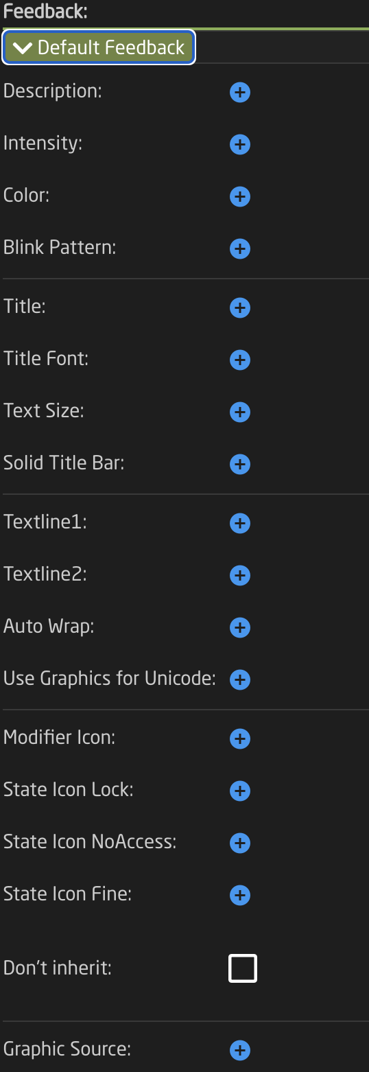
The Feedback section is about how the hardware component looks in terms of OLED display or LED color. There are two types of feedback, Default and Conditional. The default feedback is the main look of the OLEDs and LEDs. The conditional feedback is used when specific Active If conditions are used to change any part of the default feedback. The feedback can be as detailed as desired with no specific field mandatory except Index and Active If for the conditional feedback.
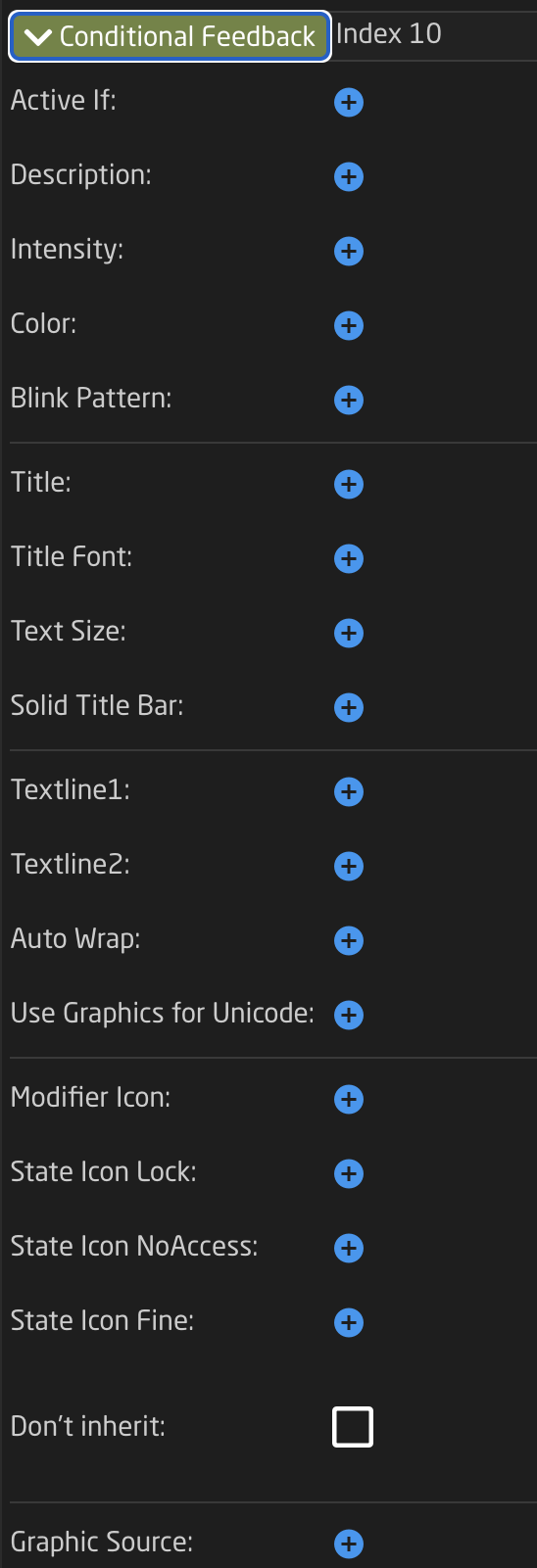
| Index |
Value assigned on feedback creation to rank the feedback's priority with higher values having higher priority in being displayed. |
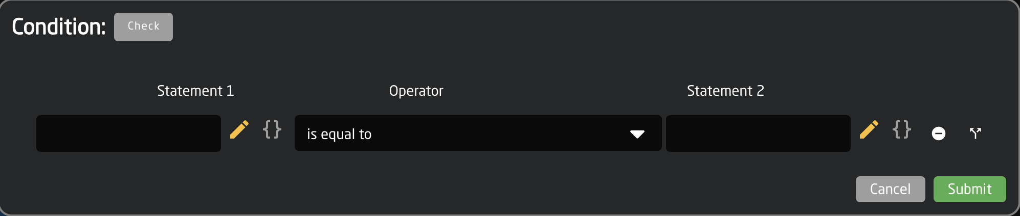
| Active If |
Conditions that need to be met for the feedback to be active.
|
| Description | Easy to understand text string of the feedback's purpose |
| Intensity | Brightness of the LED feedback; On, Dimmed, or Off |
| Color | Hue assigned to the LED feedback. Choose from predefined color, pick on a color wheel, or set based on HEX value.
|
| Blink Pattern | Pattern at which the LED should blink.
|
| Title | Text string for top 1/3 of the display, often used for a title. |
| Title Font | Font used for the title; Default, Bold, Tiny |
| Text Size | Size used for the title; Default (0,0), Small (1,1), Narrow (1,2), Medium (2,2), Large (3,3) |
| Solid Title Bar | Sets title bar's background as while and text color as black for top 1/3 of display; On, Off, No Title |
| Textline 1 | Text string for bottom 2/3 of display if Textline 2 is left blank or middle 1/3 of display if Textline 2 is used. Character length is dependent on display size. |
| Textline 2 | Text string for bottom 1/3 of display. Character length is dependent on display size. |
| Auto Wrap | Used with Textline 1 to split text into 2 lines if it is too long; on, off |
| Use Graphics for UniCode | Allows for text based character outside of the standard English alphanumeric characters. |
| Modifier Icon | Adds a modifier icon to the display; No icon, cycle, Down, Up, Hold, Toggle, OK, Question |
| State Icon Lock | Active If condition to show a lock icon in the display. Overrides the No Access and Fine icons. |
| State Icon No Access | Active If condition to show a no access icon in the display. Overrides the Fine icon. |
| State Icon Fine | Active If condition to show a fine icon in the display. |
| Don't Inherit | Advanced setting to stop the inheritance of the feedback from a parent behavior. |
| Graphic Source | Select graphic for display in place of text based display; Icon, IOReference, QRcode. Icon can be from internal library or uploaded. Additional options may exist within IOReference and QRcode. |
The Event Handlers are used to set exactly how the hardware component operates and performs the action for the parameter.
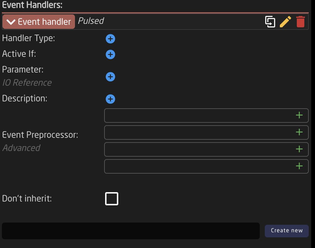
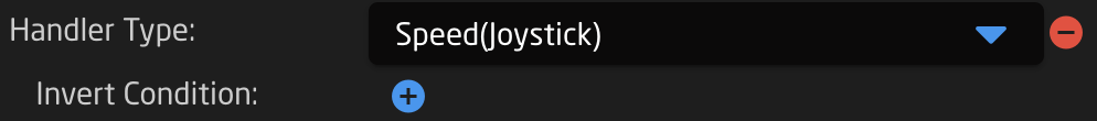
| Handler Type | Sets type of hardware component type for the component to act as; Binary (Button), Pulsed (Encoder, Roller Wheel), Analog (Fader, T-Bar, RCP Joystick), Speed (Zoom Rocker, PTZ Joystick). See below for more detail. |
| Active If |
Conditions that need to be met for the feedback to be active.
|
| Parameter | Parameter to be affected by the event handler. If left blank it will affect the main parameter. |
| Description | Easy to understand text string of the event handler purpose. |
| Event Preprocessor | Transforms incoming trigger type. Advanced |
| Don't inherit | Advanced setting to stop the inheritance of the event handler from a parent behavior. |
| Create New | Create new event handler and set name for it. |
Handler Types
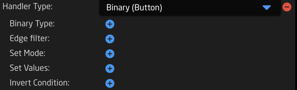
| Binary Type | Which binary the handler responds to: button press, Act Down, or release, Act Up |
| Edge Filter | Which edge of a 4-way button the handler responds to: Any edge, No edge, Top, Left, Bottom, Right, Left & Right, Top & Bottom, Encoder Click |
| Set Mode | Set, Toggle, Add, Remove, Toggle Add/Remove, Cycle Up, Cycle Down, Cycle Up and Roll Over, Cycle Down and Roll Over, Clear, Random, Sequence |
| Set Values | To set a specific value or to copy a value from another parameter |
| Invert Conditions | To set the conditions on which the action will be the invert or opposite |
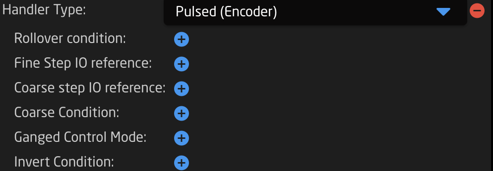
| Rollover Conditions | Conditions for the end value to rollover to the start value when cycling through |
| Fine Step IO reference | Can be a set value for size of a fine step or can be set via na IO reference |
| Coarse Step IO reference | Can be a set value for size of a coarse step or can be set via na IO reference |
| Coarse Condition | Set conditions for switching between coarse and fine mode |
| Ganged Control Mode | Way ganged control works; Set All to First, Change All Relatively |
| Invert Condition | To set the conditions on which the action will be the invert or opposite |
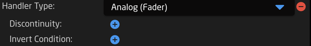
| Discontinuity | Strategy for detecting movement of a hardware component to adjust a parameters via an analog component; Double Linear, Offset, Non |
| Invert Condition | To set the conditions on which the action will be the invert or opposite |
| Invert Condition | To set the conditions on which the action will be the invert or opposite |
Within each type of event handler, there is the Event Preprocessor section for a more advanced configuration of how a hardware component should act by transforming its hardware component type.
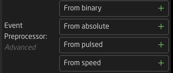
The options available with each preprocessor is dependent on the overall event handler type.
More information on Event Preprocessors coming soon.
Variables are used in many different ways and in many places within a configuration. The basic idea of a variable is it is an adjustable
 There are two types of variable: Range and Options.
A range variable is to be used with any number value from X to Y defined by the user.

An options variable is to be used with any defined text string with independently set labels.

Event Scripts
More details coming soon
Tree (Advanced)
coming soon
Raw JSON Editor (Most Advanced)
The most advanced way to build or edit configurations would be via the full JSON editor. This is technically a different page from the Configuration page, however it is only accessible via the configuration page.
For users with a background in JSON, this could be the easiest and fastest way to work with our configurations. For most users, it is best to leave this section untouched as every character can effect the functionality of a configuration.
The JSON editor can be found by clicking on the Edit Raw links in the Tree on the layers with Include Files. The JSON available via these links is the Include File layers.

The JSON editor opens on its own web browser page. From here it is possible to do a few different things.
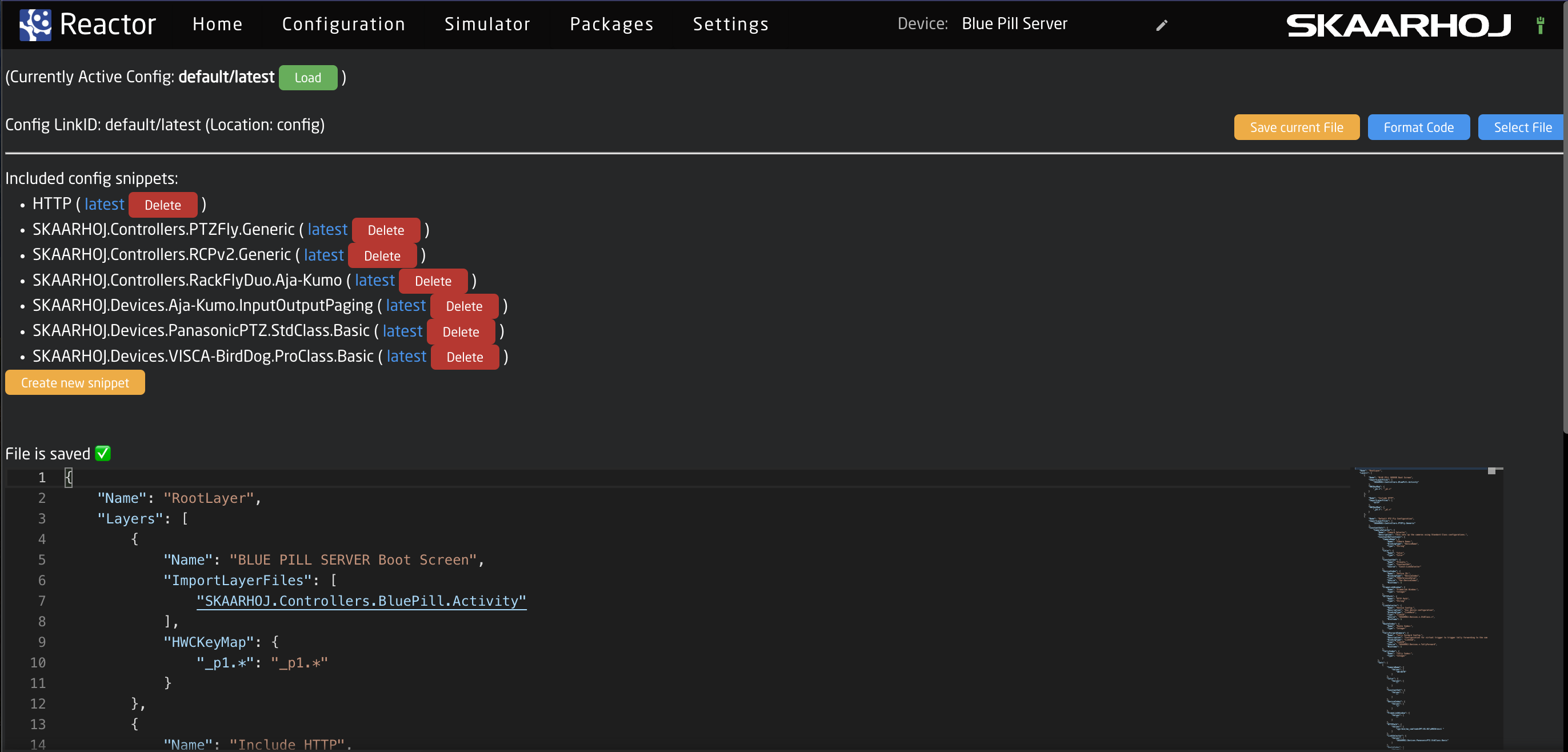
Taking a look at the top section of the page.

| Currently Active Config: | The name of the currently configuration file selected in the package. This can be shared on multiple different projects. |
| Config Link ID: | The selected link ID selected to edit. There can be multiple available per Currently Active Configuration on different layers in the tree. |
| Save Current File: | Save the current text in the JSON editor. |
| Format Code: | Format code for better layout on the page. |
| Select File: | Allows for the selection of a different configuration file to load into the currently selected layer that has an include layer. See image below. |
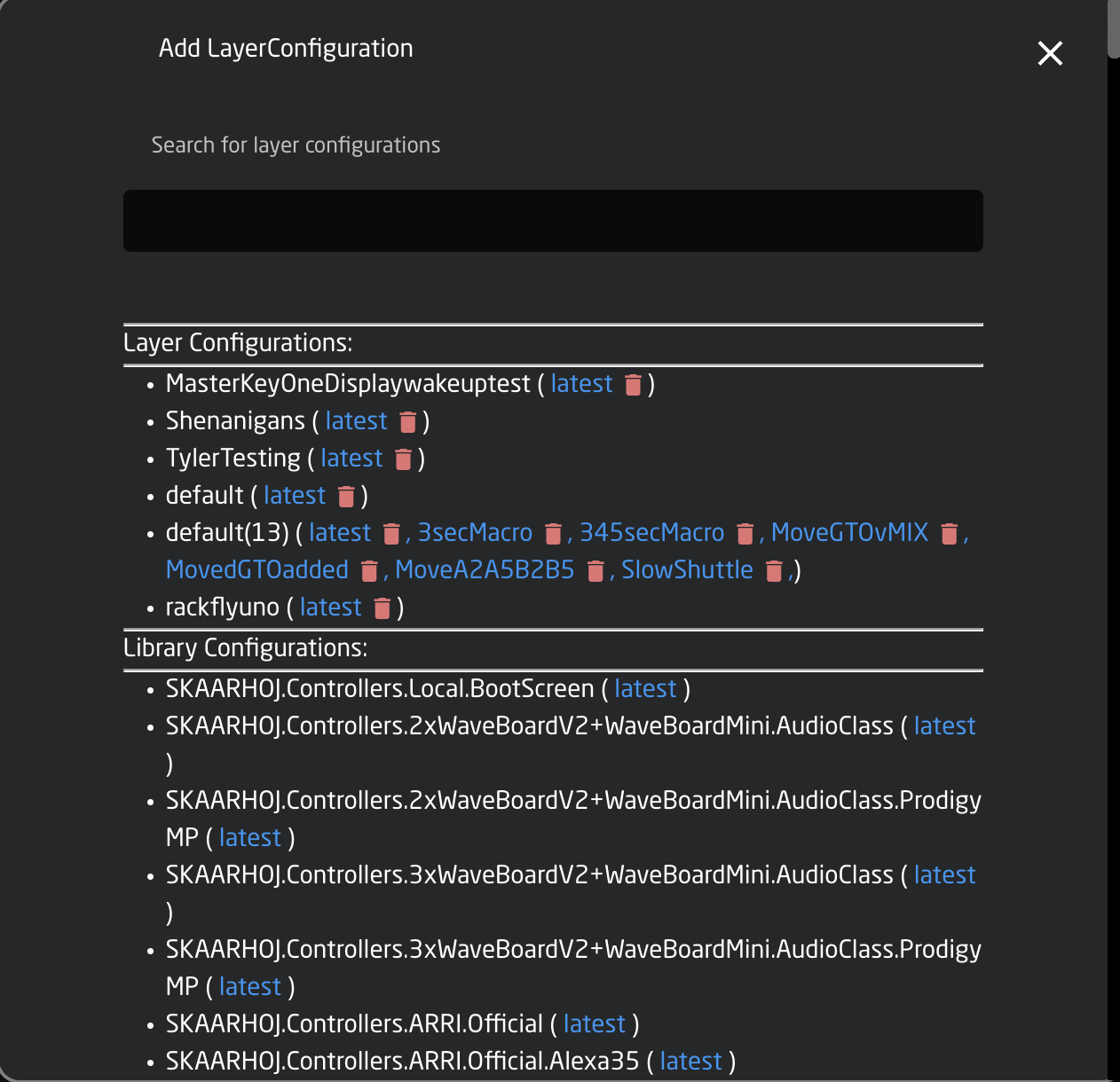
| Layer Configurations | Configuration files available on the Blue Pill device |
| Library Configurations | Configuration files available from Skaarhoj |
The middle section of the page contains the available different Snippets or include files within the selected configuration.
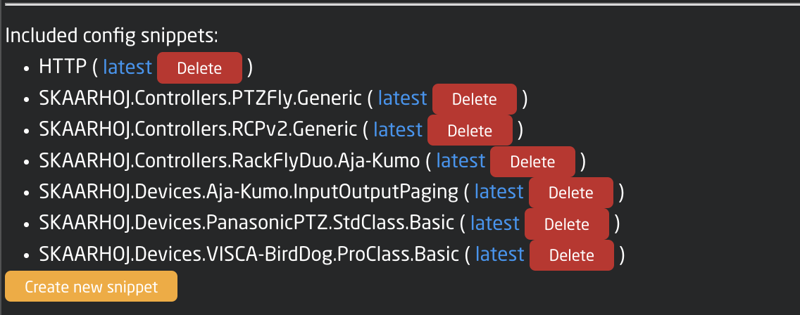
| Snippet Name | The include file name for that specific snippet. |
| Latest | Loads the latest version of the snippet into the JSON editor |
| Delete | Deletes the snippet |
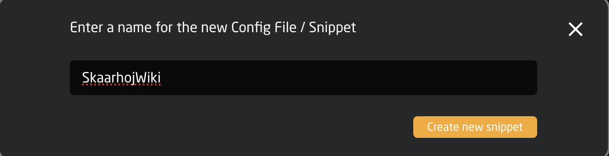
| Create new snippet | Allow for the creation of a new snippet file. See image below. |
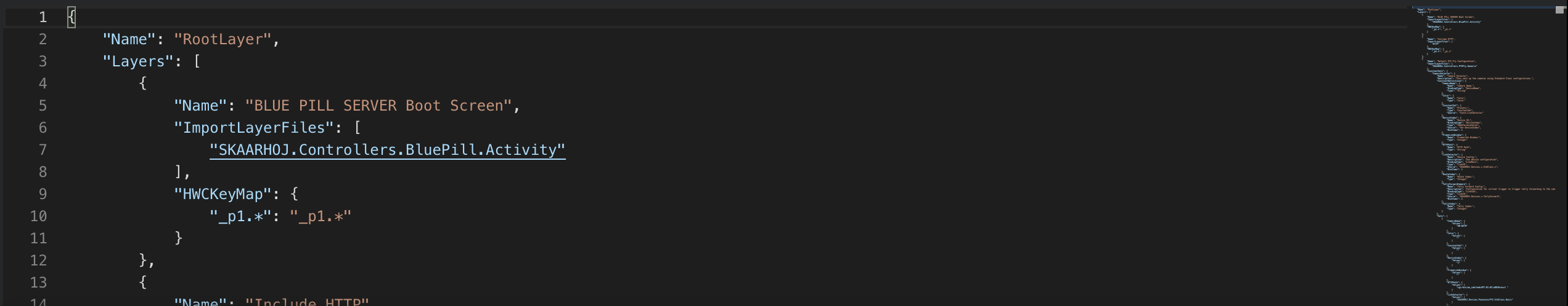
The bottom section is the JSON editor tool. Each line is numbered for easy reference and differentiation. The right hand side of the editor is a miniature version of the editor to quickly jump down to different sections for navigation.
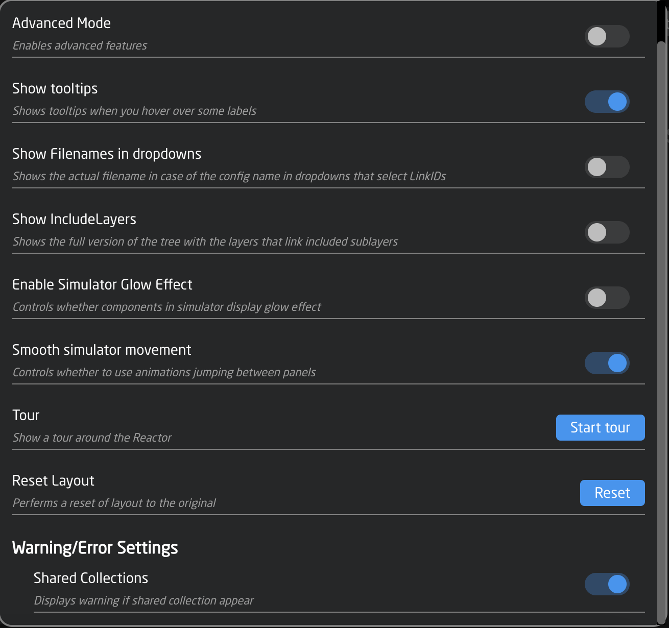
Settings Tools
Located in the Settings on the Configuration page are some tools for use when working on the configuration page.
These tools can be opened by click on the cog wheel in the lower right corner of the page.
The available tools are as follows:
Simulator
Reactor has a built in simulator too. There are two ways to do simulations in Blue Pill, through the Simulator page and in the Configuration page.
There are some limitations to simulations and it is not meant to be a replacement for a hardware panel but as a helpful tool.
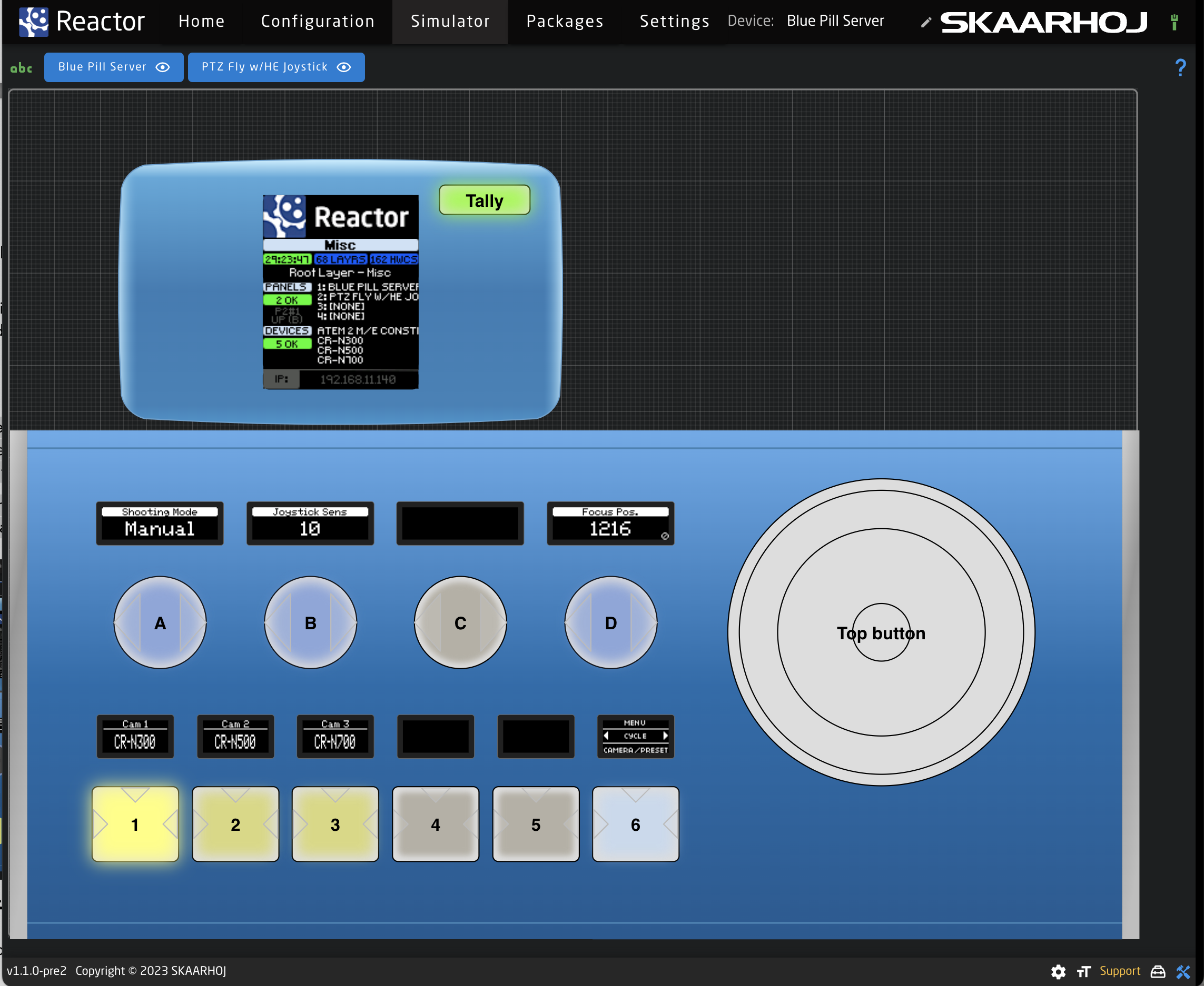
Simulator
On the Simulator page, an interactive graphical display of each panel is present. The current mapping of each controller is visible. What is seen in the simulator will be reflected on any attached panels and will control any attached devices. Devices will be effected even if the panel is being fully simulated and is not physically present.
It is possible to simulate both the panel and the device from a stand alone Blue Pill to get an idea of what that mapping is like and what actions are available. Some data is not able to be simulated as it relies on the connected device for details.
Simulation via Configuration Page
In the Configuration page, it is possible to toggle between simulation and configuration modes to test the work in progress. While in simulation mode, it is not possible to add to the configuration on the Configuration page.
The simulators display the panels as they are arranged in the Graphical View of each panel group (see Panels sections for more information) and per group.
It is possible to limit which panels are seen in the simulation by selecting or deselecting the name on the panel at the top of the page via the eye icon. Clicking on the name will put that specific controller in center focus on the page.
![]()
Resizing:
- Option + mouse drag to navigate up, down, left and right
- Mouse scroll -> adjust zoom level
Right Click Options on HWC:
- Hold Down
- Release Button
- Long Press
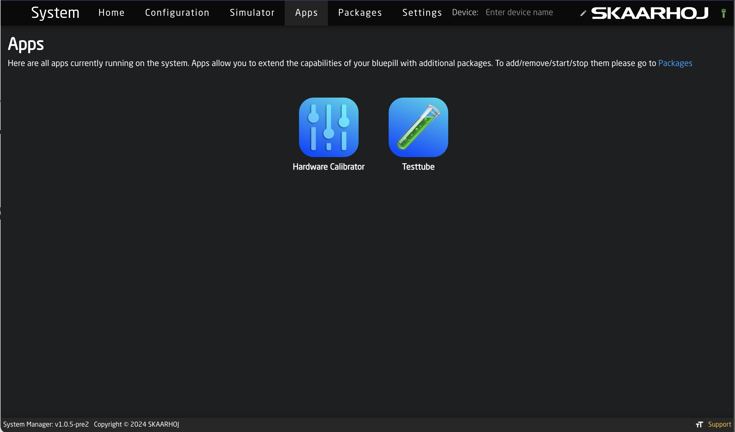
Apps
Apps allow you to extend the capabilities of your Blue Pill with additional packages. These packages not designed to control specific devices like other packages available on the packages page.
Packages
Blue Pill being a Linux system has a number of system settings and a package management interface. From this interface it is possible to add new, remove unneeded, update, and monitor the packages needed to control the panels and the devices.
Required Packages
The following Packages are needed for Blue Pill operation.
hardware-manager is the application that facilitates access to the hardware features of the Blue Pill. On an RCP Pro with Blue Pill Inside the hardware-manager application creates the Raw Panel based access to the hardware components of the RCP Pro (so even when Blue Pill runs natively on a controller like RCP Pro, it is still using a network socket to talk to the hardware on the panel, so in that way it is no different from connecting to external panels!).
system-manager is the system management UI for skaarOS.
Reactor is what most will generally think of as the Blue Pill. This is the platform where panels, devices, and configurations are added.
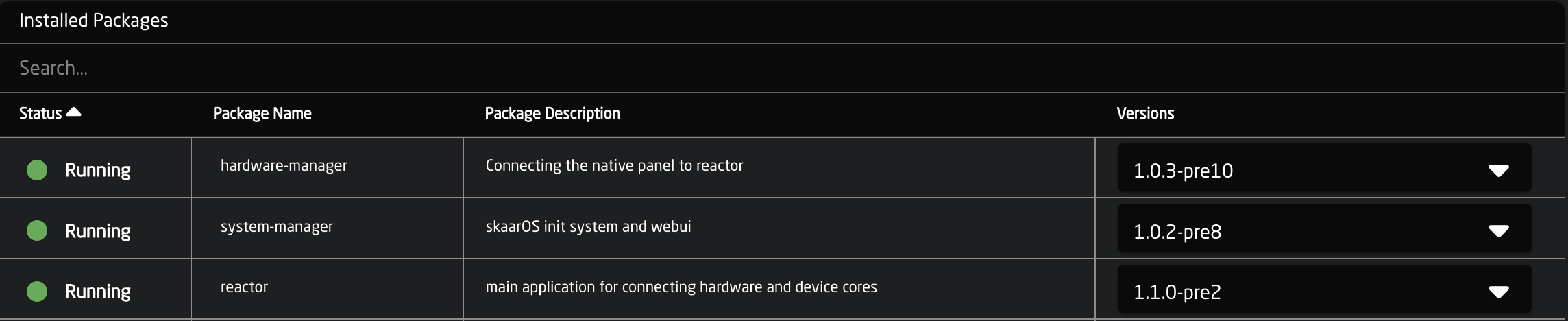
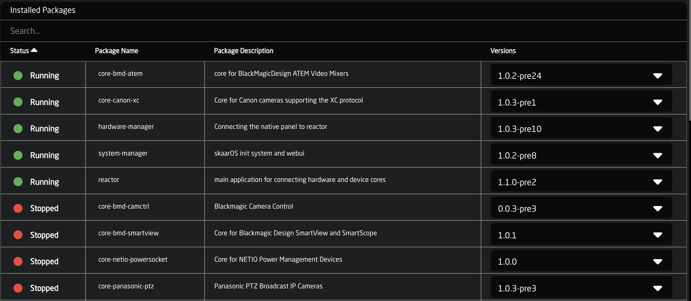
Installed Packages
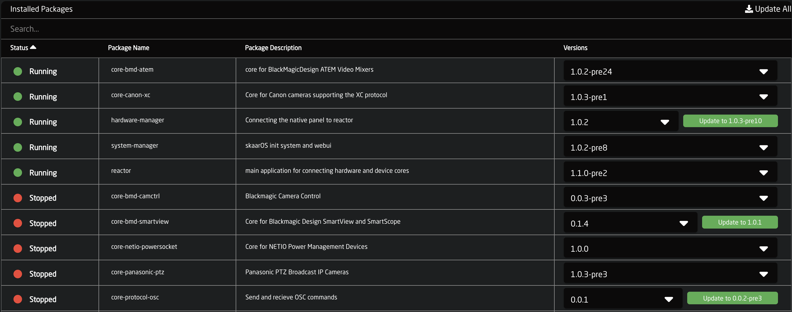
The overview page shows which packages are currently installed and in which version; whether they are running or not. In this screenshot the Blue Pill has device cores for BMD Atem, Canon XC Protocol, BMD Camera Control, BMD Smartview, NetIO Power Socket, and Panasonic PTZ cameras. They are all stopped except the BMD Atem and Canon XC packages. An installed core will generally stop running when there are no devices that use it currently in the devices section for project. This is designed to save processing power while allowing for packages to be loaded onto the Blue Pill for later use.
Available Packages
Not much different from the list of installed packages, are the available packages. This list is growing all of the time as we add new integrations.
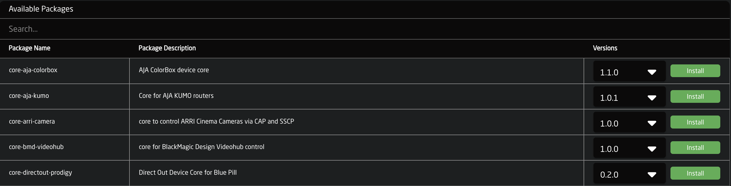
When connected to the internet the needed package for a device core will generally auto install when a device associated with it is selected via the devices section of the Home screen.Installing new packages requires internet access as they are pulled from an online storage with applications we have published.
Please note, prerelease updates are only available when using the Show Pre-Release toggle at the top of the page.![]()
If working in a offline environment, it is possible to manually upload a device core package from a file on your computer. This is done from the Upload and install package button at the bottom of the Packages page.

All of our current stable release and prerelease of our cores are available on our website devices.skaarhoj.com.
Package Details
Clicking an installed package brings opens the settings page of the package.
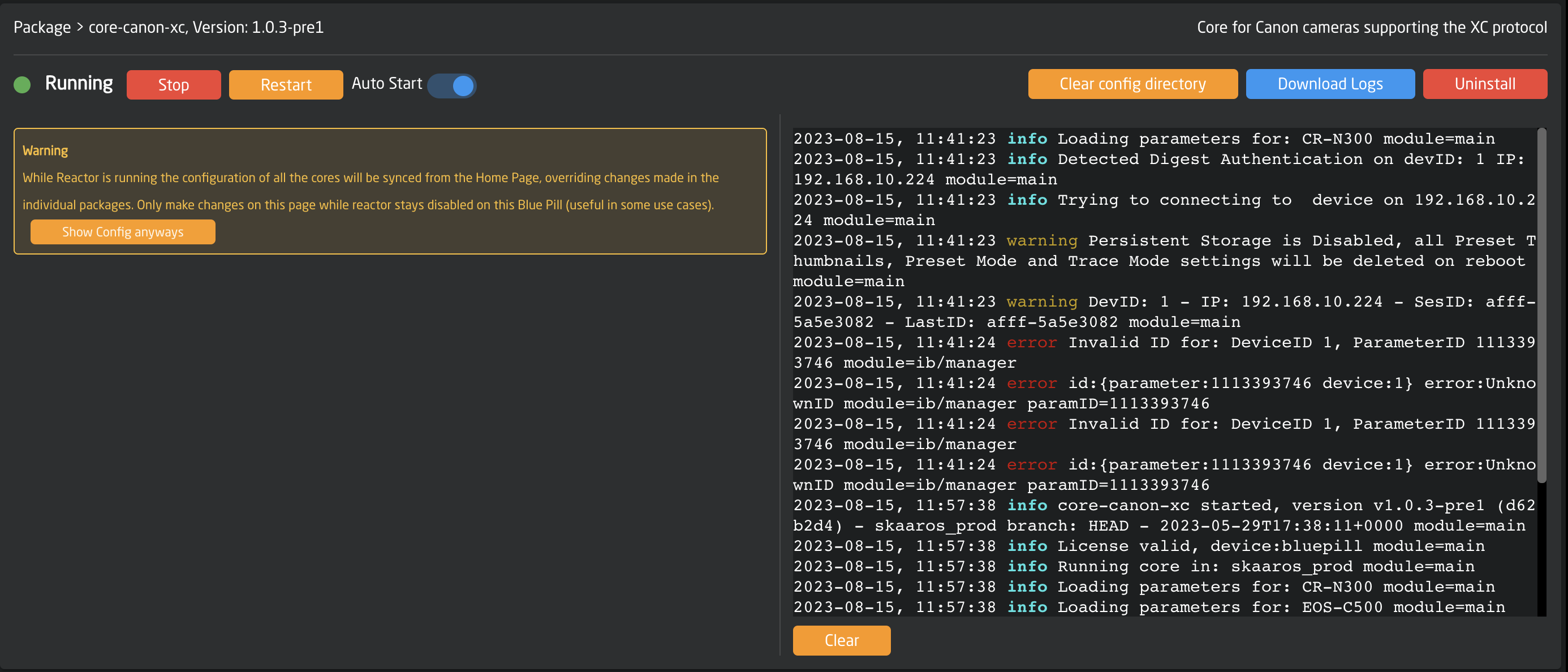
From the Package/Core Settings page it is possible to see the current status, stop or restart, and set Auto start. This can be a helpful tool if the core is not acting properly.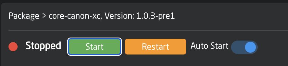

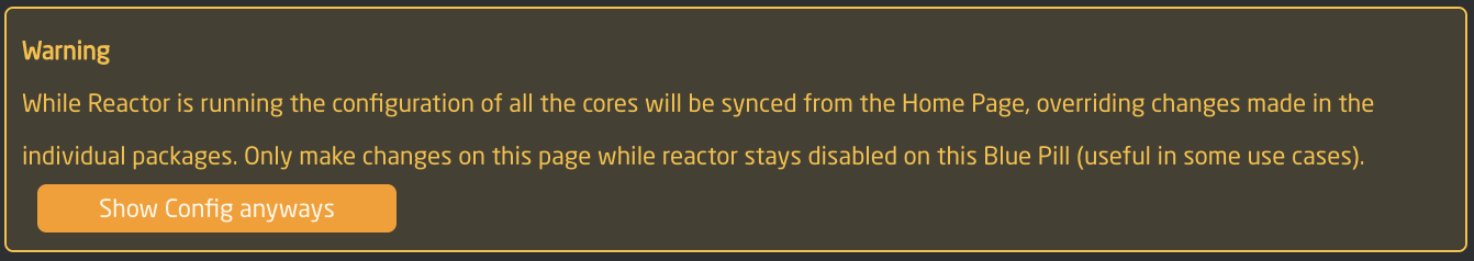
All connected devices to the package are not visible by default, they can be seen, along with their current settings, by clicking on Show Config anyways in the Warning box. While it is possible to update them from this page, it is advised to add and adjust them from the Home page, as the data is synced from there.
On the the left the package logs can be seen and downloaded. This can be used for troubleshooting and may be requested by the support or development team for diagnostics.
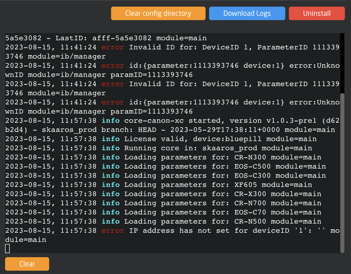
Clear Config Directory will delete everything that was saved onto the Blue Pill by that specific package and return it to its default settings. This can sometimes be useful if the device core packages is not running properly.
Clearing the Config Directory for the Reactor package will erase all projects on the device. It is suggested to export any needed project before clearing the config directory of that package.
It is also possible to completely Uninstall a package from this page. Doing so will not remove previously connected devices, but will cause them to be disconnected.
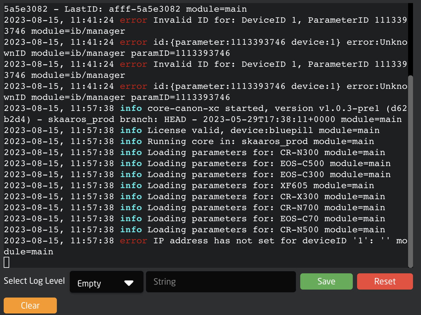
When setting the Blue Pill into advanced mode, filtering options become available for the core logs.
Updating Packages
Updating packages or reverting to older versions of packages is simple.
Generally Updating or Downgrading a device core package requires internet connectivity to our servers, however we do offer an offline update method.
Packages with updates available with updates available with have a green UPDATE TO X.X.X button next to the current version. Pressing the update button will update that individual package. Pressing the Update All button on the top will run all available package updates.
Please note, prerelease updates are only available when using the Show Pre-Release toggle at the top of the page.![]()
To revert back to a previous version of a package click on the drop down in the Versions column and select the desired version.

It can be necessary to manually upload a package file from your computer, this could be because the panel is used in an offline workflow or because support has sent a package file for the customer to test. This is done from the Upload and install package button at the bottom of the Packages page.
All of our current stable release and prerelease of our cores are available on our website devices.skaarhoj.com.
Special Packages
devicecore-connector is a bridge used on this particular Blue Pill that will make the device cores on it available to the outer world. This is used when for an architecture where separate Blue Pills run the device cores locally to load balance or manage network latency - or in the simple case of Blue Pills with SKAARHOJs series of extension cables which bridges connectivity to legacy serial systems (RS-422, RS-485, RS-232 and analog voltages for lens control etc.). In those cases, having a device core run locally on that Blue Pill is not only necessary because it needs to talk directly to UARTs, but it also means that single-master serial devices (and, this is what most of them are…) are available for multi-master access via the device core TCP interface.
More Special Packages and details coming soon...
Licensed Packages
Most of our devices cores do not require any special permissions or licenses to use. They can be installed when needed as your needs change. However there are some packages that do require a Skaarhoj assigned license. These generally involve using a 3rd Party Panel in your Blue Pill workflow.
If you are unsure if the package you need requires a license or license fee please reach out to support@skaarhoj.com.
Some examples of licensed packages are:
Device Core Link
TCP Link for Atem
HID Devices
StreamDeck
X-Keys
The licensed packages can all be downloaded and installed but have a run time of 10 mins. This allows for our customers to test the packages to see if they will meet their needs before needing to purchase the license. To continue the testing, restart the device core package, wait 1 minute, then you can use it again for another 10 minutes.
Settings
On the System screen is additional system related information and tools.
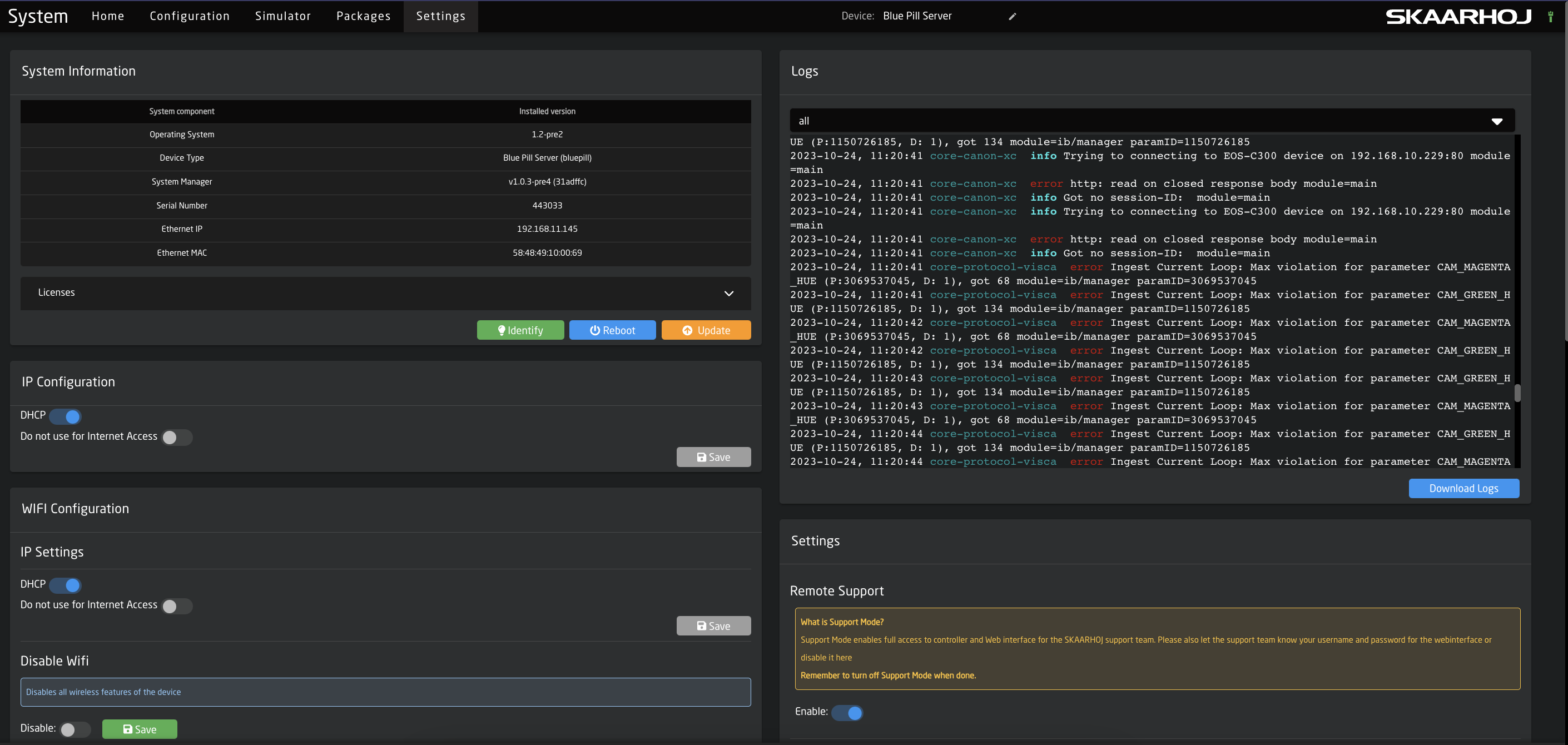
System Information
The overall System Information is displayed in this section including the Installed OS Version number for the main components, the serial number, the current IP information, the MAC address, and all assigned licenses to the device. There is the option to Identify the unit, by having the small led next to the ethernet port light red for 30 seconds, reboot the unit, or update operating system. 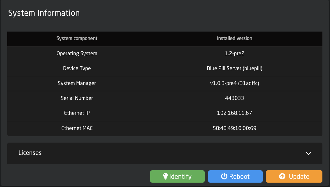
In Advanced Mode there is the option to perform a hard reset of the Blue Pill.

Please note, doing a Reset will erase all installed packages, IP configuration, and any projects. This will return the Blue Pill to factory settings. It is not possible to recover any lost information after a Reset which is why it is hidden in Advanced Mode.
Licenses
See next sections for detailed information.
Licenses
Some specialized device cores or applications require a license (and possible license fee) to use outside of a short test period (usually 10 mins). All licenses assigned to a Blue Pill can be seen under the system information section. Each Blue Pill device will come with at least one assigned license for its general operation. For standard Skaarhoj panels that will be the "base" license. This may be different for more specialized panels.

Licenses can be assigned by the Skaarhoj support team. Please reach out to support@skaarhoj.com for information on any specific license and if there is an applied license fee.
After a license is assigned by the support team, it may be necessary to refresh the Settings page a few times to see the assigned license.
Internet access is needed for the Blue Pill device to touch the Skaarhoj server to register an assigned license. If that is not an option, please let the support team know.
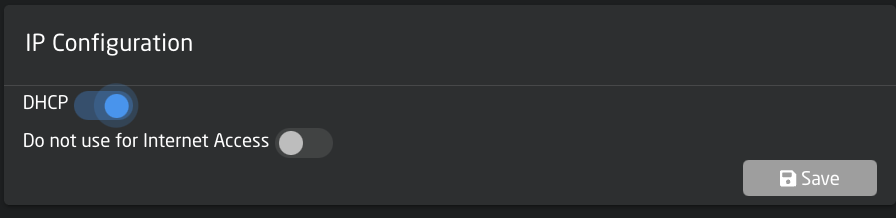
IP Configuration
There are two options for setting the IP configuration of the Blue Pill, DHCP or Manual. To switch to Manual IP Configuration, toggle off DHCP, enter the desired IP network information, and press save.
By default the IP is set to DHCP, if DHCP is not available on the network a fallback IP address of 192.168.10.99 will be used.

Please note, changing the IP information will cause the web interface to lose connection as the IP address has been re-assigned.
By enabling the "Do not use for internet Access" toggle, you can turn off general internet connection to the Blue Pill device on networks that have general internet access.
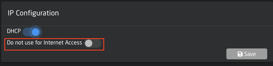
When Internet access has been restricted the ethernet cable icon in the top right corner of the screen will have changed from green to red.

Please note, internet access is needed to install, update, or revert packages. For offline updating please check out the Updating Software section of our Wiki.
WiFi Configuration
There are multiple ways the Blue Pill can interact with WiFi. There is the IP Settings for when the Blue Pill is connected to a WiFi network, the Access Point to enable a local access point to connect to the Blue Pill, and Connection Settings to connecting the Blue Pill to a local WiFi network.
WiFi is not intended as the main way to use the Blue Pill. Blue Pill is encapsulated in metal and the reach of the WiFi antenna will be very short, so consider it for very localized access, but sufficiently useful to connect to the WiFi of a camera just next to the Blue Pill device. Or to enable the WiFi access point for mobile device management.
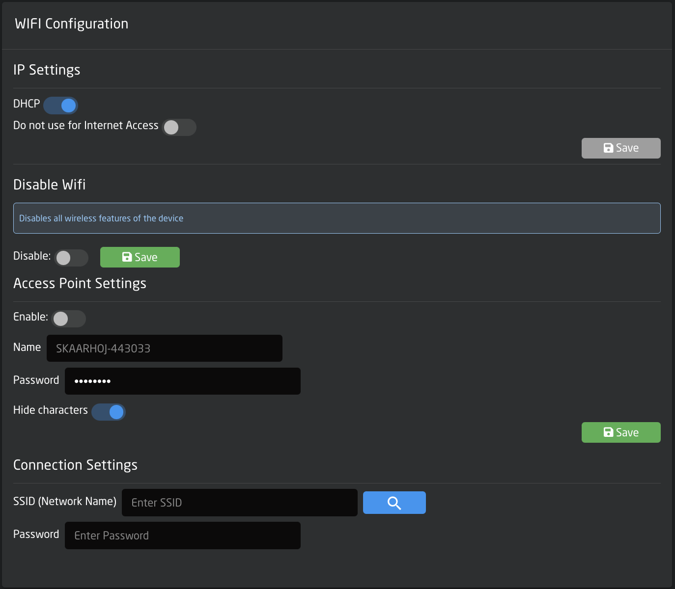
IP Settings
There are two options for setting the IP configuration of the Blue Pill, DHCP or Manual. To switch to Manual IP Configuration, toggle off DHCP, enter the desired IP network information, and press save.
By default the IP is set to DHCP, there is no fallback static IP address for WiFi.
Please note, changing the IP information will cause the web interface to lose connection as the IP address has been re-assigned.
By enabling the "Do not use for internet Access" toggle, you can turn off general internet connection to the Blue Pill device on networks that have general internet access.
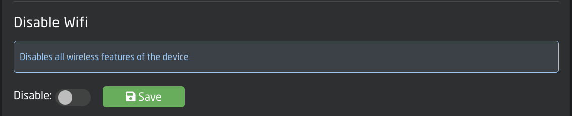
Disable WiFi
Enabling the Disable WiFi feature will disable all wireless features from the Blue Pill device.
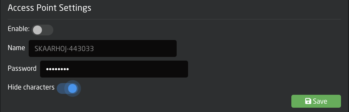
Access Point Settings
Used to access the Blue Pill via an internal WiFi to establish a connection and set the needed network information for regular connection. In this section the Access Point can be enabled/disabled and the password set. The web interface is then accessed at the IP address: 192.168.4.1 By default the password is skaarhoj. See the Getting Started section for more information.
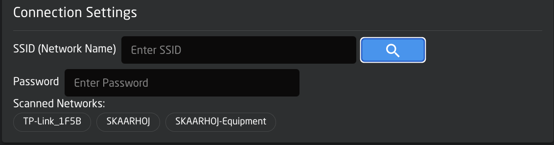
Connection Setting
Used to connect the Blue Pill to the local WiFi network. Pressing Scan will search for available networks. Clicking a network that appears after a scan will allow for the entering of the needed password to establish the connection.
Please note connecting the Blue Pill to both the wired and wireless networks for internet access can cause instability in the connection.
Logs
The logs are used mainly by the development team to help debug any problems. Each device core has its owns logs section but it is can all be seen in the systems logs section. Clicking the drop down will allow for the filtering of specific device cores/packages.
Frequently when writing to support, they will request the logs to be sent along with other information. The full panel logs can be dowloaded from the Logs section of the Settings page.

Remote Support
Enabling Remote Support mode will allow the SKAARHOJ support team to remotely access the Blue Pill. By default this is disabled for security reasons as it gives SKAARHOJ access to your network.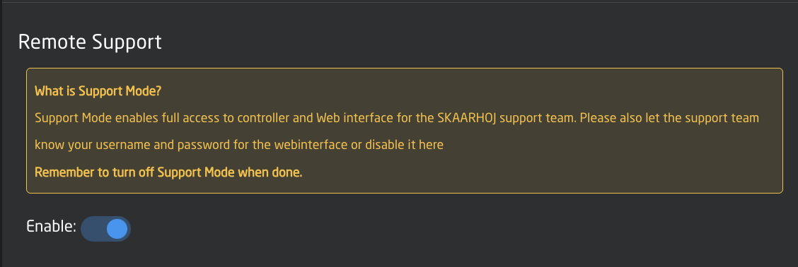
Please note, wired internet access needs to be enabled for support to access the Blue Pill.
USB-A
USB-A switches between the Micro USB port (on by default for service such as connection to the SKAARHOJ firmware application or re-flashing the entire unit in severe cases) and the USB-A port which is used, for example, by our FrameLink application to grab and utilize frames for thumbnail display in panels. See the Thumbnail Presets section for more information about the FrameLink application.
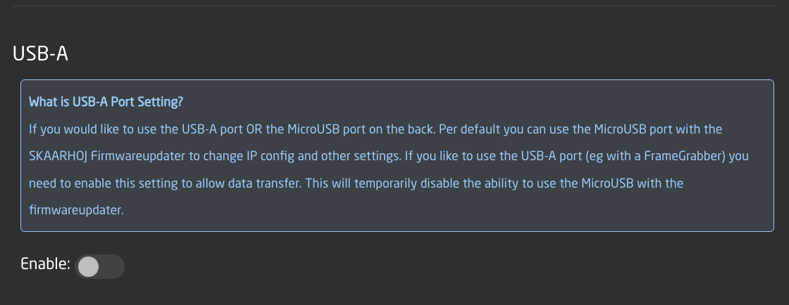
Please note, when USB-A is enabled, the USB-Micro port is disabled.
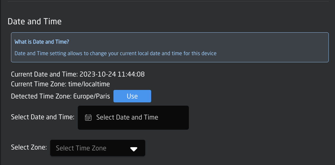
Date and Time
Date and Time allows for setting the current date and time on the Blue Pill. This can sometimes be needed for the device to check NTP when connecting to our servers for updates.
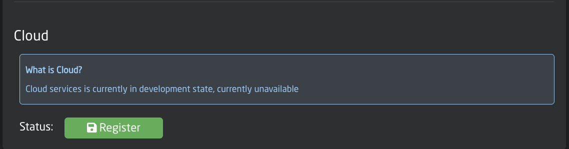
Cloud
Cloud has not yet been implemented and is coming soon.
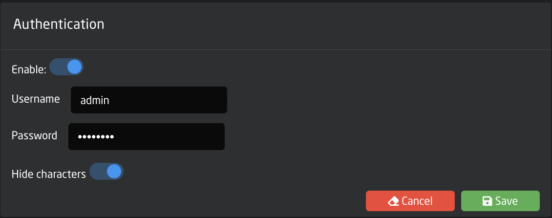
Authentication
Authentication allows for the setting of a username and password to restrict access to the Blue Pill web interface. By default the Username is admin and the password is skaarhoj This feature can also be disabled.