Settings Tables
Examples and descriptions of settings tables
- Audio Channel Config
- Camera Select
- Playlist
- Routing Panels
- Routing Triggers
- Switcher Inputs
- Tally Forwarding
- Transition Types
- Quick Controls
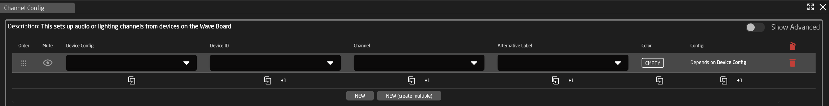
Audio Channel Config
An example of an audio channel config can be seen below. These can be different depending on the selected configuration and device. From here the order on the audio channel order will be set as well as the desired name on the displays and button color.

|
Column |
Description |
|
Order |
Allows for quick rearranging of channel order. Right clicking on order will allow for deleting the row. |
|
Mute |
Allows for removing access to a specific channel or to leave a blank spot on the panel |
|
Device Config |
Ties the fader to a specific device config. |
|
Device Index |
Ties the fader to a specific device associated with the config. See Device Details for the device index number. |
|
Channel |
Ties the fader to a specific channel in the selected device. See device parameter list for available channel number for the specific device. |
|
Alternate Label |
Customizable name to appear on the displays. Character limit is determined by size of display and can vary. |
|
Color |
Sets the button feedback color. Color options are: OFF, WHITE, WARM, RED, ROSE, PINK, PURPLE, AMBER, YELLOW, DARKBLUE, BLUE, ICE, CYAN, SPRING, GREEN, MINT. |
|
Config |
Setup some extra configurable attributes on some specific device configs. |
|
|
Delete the row. |
|
|
Duplicates the details of the column. |
|
|
Increments the number in the column by +1. |
|
|
Adds a new line to create additional fader channels. |
|
|
Opens a table to create multiple new fader channels. See Batch Create section. |
Batch Create

| Amount of Rows to Create | The number of additional rows to be created. |
| Column Name | Which settings table row's info being referenced. |
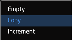
| Populate Behavior | Select if the settings table row is to be empty, copied, or incremented by 1.
|
| Focus Row Value | Current value of the settings table row to be left empty, copied, or incremented in the new rows. |
Camera Select
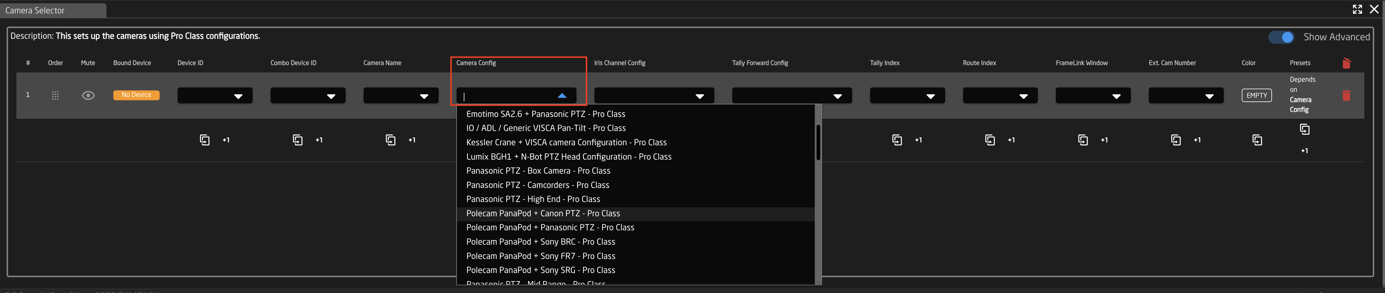
An example of a setup table would be a camera selector and can be seen below. These can be different depending on the selected configuration. From here the order on the camera selector row of the panel will be set as well as the desired name on the displays.

|
Column |
Description |
|
Order |
Allows for quick rearranging of camera order. Right clicking on drag will allow for deleting the row. |
|
Mute |
Allows for removing access to a specific camera or to leave a blank spot on the panel |
|
Bound Device |
Allows for the selecting of a specific connected camera |
|
Device ID |
Ties the camera selector to the specific device. This is found in the Devices section. Each device will have a unique device number per device core. This box should auto-populate when a camera is selected in binding |
|
Combo Device ID |
The Device ID associated with the combo device (usually a pan/tilt head) when creating a combo device to present as a single device on the panel. |
|
Camera Name |
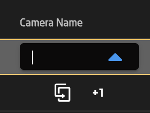
Customizable name to appear on the displays. Character limit is determined by size of display and can vary. |
|
Camera Config |
Selects the protocol based configuration associated with camera. Needed protocol can be seen in the Devices section, each device is grouped into their native protocols. Double check the correct configuration is selected. Improper selection will effect camera control. |
|
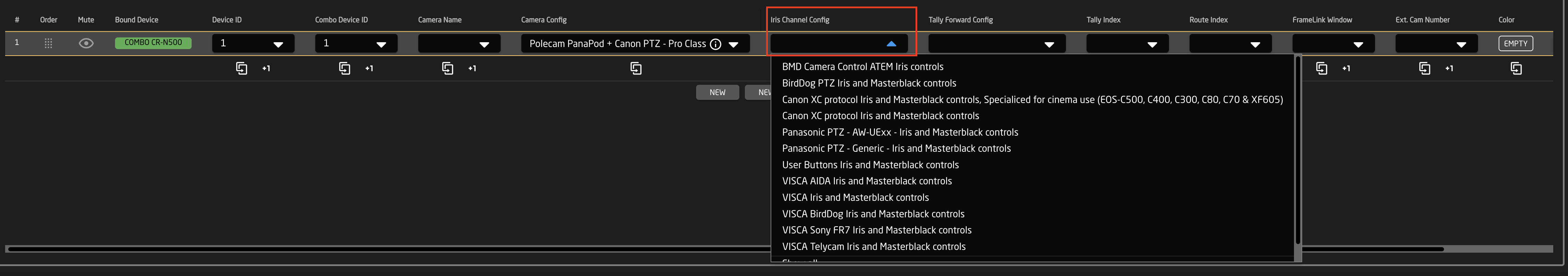
Iris Channel Config |
Selects the needed protocol for Iris/Master Black control. For cameras without a variable lens this will follow the same protocol as the device. For cameras with a variable lens, select the protocol for the attached lens. Not available on all configuration classes. |
|
Tally Forward Config |
Selects the needed protocol for Tally to the cameras. . Not available on all configuration classes. |
|
Tally Index |
Sets the Tally Index number to connect with associated tally source device. See Blue Pill/Reactor Manual for more information. This column does not need to be filled out for standard operation. |
|
Route Index |
Sets the Route Index number to connect with associated routing device. See Blue Pill/Reactor Manual for more information. This column does not need to be filled out for standard operation. Additionally, if needing to route to multiple destinations, additional cells need to be added. See instructions below. |
|
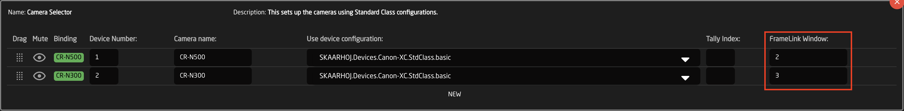
FrameLink Window |
Sets the FrameLink Window value associated with the FrameLink device core for use with FrameLink compatible devices. See Blue Pill/Reactor Manual for more information. This column does not need to be filled out for standard operation. |
|
Ext. Cam Number |
Sets an External Camera Select number that is used in a virtual trigger to allow for syncing the camera select between multiple panels. |
|
Color |
Allows for the selecting of a custom color for the camera select buttons. This would be overridden as needed if Tally Forwarding from a switcher is set up. |
|
Presets |
Customize name and color for presets associated with specific camera configurations. |
|
|
Delete the row. |
|
|
Duplicates the details of the column. |
|
|
Increments the number in the column by +1. |
|
|
Adds a new line to create additional camera selects. |
|
|
Opens a table to create multiple new camera selects. See Batch Create section below. |
Adding a New Cell to a Column
Some of the settings table columns allow for multiple multiple cells to be added per row. To add or delete a cell, right click on it to select Add cell or Delete cell.

Batch Create

| Amount of Rows to Create | The number of additional rows to be created. |
| Column Name | Which settings table row's info being referenced. |
| Populate Behavior | Select if the settings table row is to be empty, copied, or incremented by 1.
|
| Focus Row Value | Current value of the settings table row to be left empty, copied, or incremented in the new rows. |
Combo Device Set Up
For camera control we have made a large number of default configuration to control combo devices. These are most frequently a camera plus a pan/tilt head or pedestal.
Combo devices using our default configurations are set up from the camera select.
- Enable Show Advanced
This can be done after adding the camera or start with a blank line in the camera selector. Holding Shift while pressing New will allow for you to add a blank line in the table without first selecting a device.
- In the Camera Config drop down, select the desired combo device configuration.

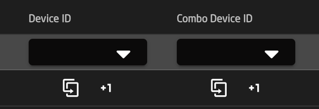
- To tie the configuration to the specific devices, enter the Device ID numbers associated with them in the Device ID and Combo Device ID column. The Device ID will be for the camera and the Combo Device ID will be for the other non camera device. You can find the specific Device ID number for each device in device details.

- Make sure the Iris Channel config is set to match the camera that is being control.

- Set the Camera Name to whatever fits the operator's workflow.

- Other fields are to be filled out based on need according the table at the top of the page.
- The combo device should not be set up and ready to test.
FrameLink Window
 The Skaarhoj Frame Link package combined with an HDMI Video Capture card allows for thumbnail presets images on compatible SKAARHOJ panels like the Frame Shot from any HDMI source.

At time of writing we have only tested the HDMI Video Capture stick below so would not be able to say how other models perform.
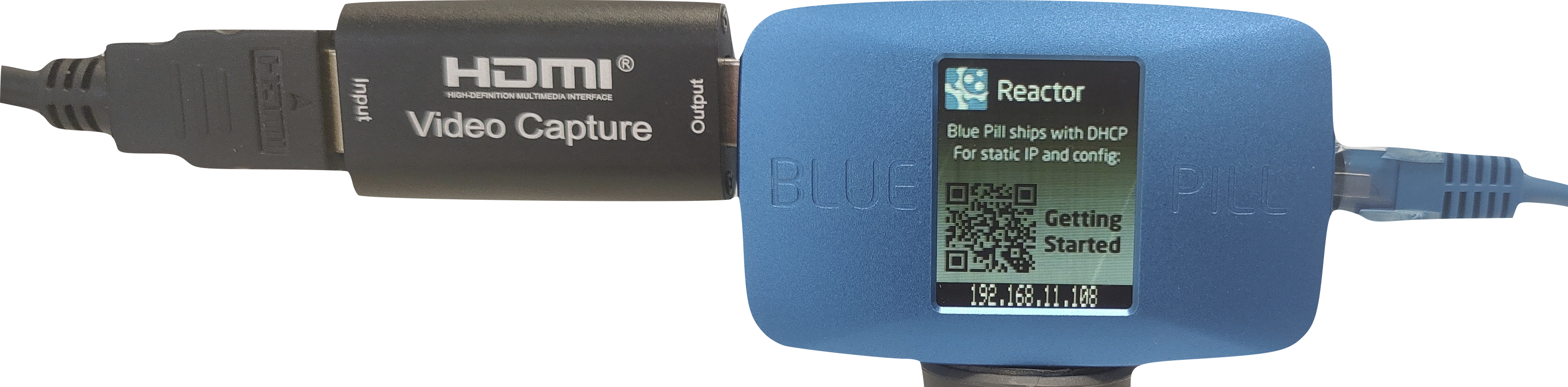
Please note, some PTZ camera models natively support thumbnail presets like the Canon CR-N500. The FrameLink package, Framelink Window, and the HDMI Video Capture stick are not needed for those models of cameras. This is only for cameras or other devices that do not natively support this feature.
The breakdown of the 21 FrameLink Window options is seen below. The incoming HDMI feed can be broken up into either full picture, a 2x2 grid, or a 4x4 grid.
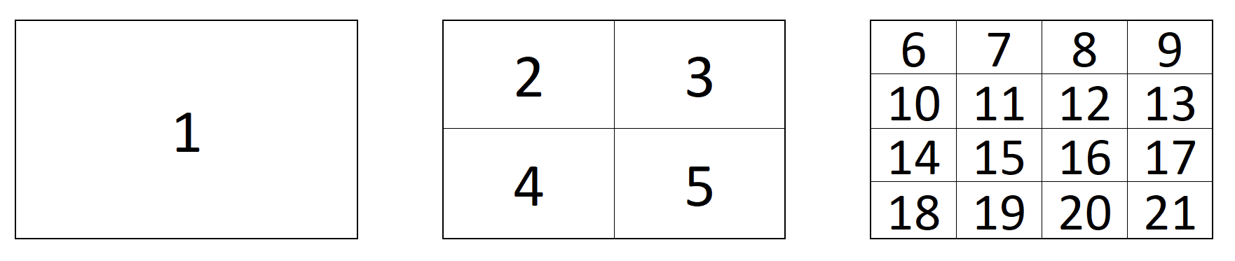
Entering the corresponding squares number into the FrameLink Window section of the Camera Selector’s settings table will use that portion of the image as the thumbnail for the preset. In general the grids are for use with a multiviewer.
Playlist
Details coming soon.
Routing Panels
An example of a router panel set up can be seen below. These can be different depending on the selected configuration and device.

Device Selector

|
Column |
Description |
|
Order |
Allows for quick rearranging of router order. Right clicking on order will allow for deleting the row. |
|
Mute |
Allows for removing access to a specific router or to leave a blank spot on the panel |
|
Bound Device |
Allows for the selecting of a specific connected routing device. |
|
Device Index |
Ties the selector to a specific device associated with the config. See Device Details for the device index number. |
|
Device Name |
Customizable name to appear on the displays. Character limit is determined by size of display and can vary. |
|
Description |
Customizable description. Character limit is determined by size of display and can vary. |
|
Device Configuration |
Selects the protocol based configuration associated with the router. Needed protocol can be seen in the Devices section, each device is grouped into their native protocols. |
|
Setting |
Setup some extra configurable attributes on some specific device configs. For routers this is usual Input and Output mapping. See Settings section below. |
|
|
Delete the row. |
|
|
Duplicates the details of the column. |
|
|
Increments the number in the column by +1. |
|
|
Adds a new line to create additional routing select. |
|
|
Opens a table to create multiple new routing selects. See Batch Create section below. |
Batch Create

| Amount of Rows to Create | The number of additional rows to be created. |
| Column Name | Which settings table row's info being referenced. |
| Populate Behavior | Select if the settings table row is to be empty, copied, or incremented by 1.
|
Settings

|
Column |
Description |
| Order | Allows for quick rearranging of input/output order. Right clicking on drag will allow for deleting the row. |
| Mute | Allows for removing access to a specific input/output or to leave a blank spot on the panel |
| Output Number/Input Number | Ties the selector to the specific input/output. This is found is determined by the individual router. |
| Alternative Label | Customizable name to appear on the displays. Character limit is determined by size of display and can vary. |
| Color | Sets the button feedback color. Color options are: OFF, WHITE, WARM, RED, ROSE, PINK, PURPLE, AMBER, YELLOW, DARKBLUE, BLUE, ICE, CYAN, SPRING, GREEN, MINT. The format for color selection is all large letters with no spaces between words. |
| Delete the row. |
Advanced Layout Configurations
The layout of the routing configurations are able to be change within the configuration. Within the Advanced Layout Configurations settings table, it is possible to set up page sizes and offsets for each of the configurations as well as set up a prefered order of the layouts. Not all columns are used for each device configuration.

|
Order |
Allows for quick rearranging of layout order. Right clicking on drag will allow for deleting the row. |
|
Mute |
Allows for removing access to a specific layout or to leave a blank spot on the panel |
|
Layout Number |
Out internal reference number for the layout |
|
Label |
Text in displays of panel |
|
Input Page Size |
Input Page Size |
|
Input Page Offset |
Input Page Offset |
|
Output Page Size |
Output Page Size |
|
Output Page Offset |
Output Page Offset |
|
Level Page Size |
Level Page Size |
|
Level Page Offset |
Level Page Offset |
|
Preset Recall Page Size |
Preset Recall Page Size |
|
Preset Recall Page Offset |
Preset Recall Page Offset |
|
Preset Store Page Size |
Preset Store Page Size |
|
Preset Store Offset |
Preset Store Offset |
|
Salvos Page Size |
Salvos Page Size |
|
Salvos Page Offset |
Salvos Page Offset |
|
|
Delete the row. |
|
|
Duplicates the details of the column. |
|
|
Increments the number in the column by +1. |
Routing Triggers
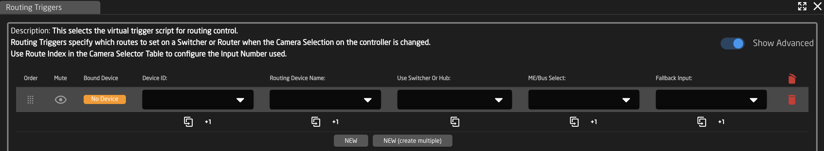
An example of a Routing Triggers settings table can be seen below. From here the camera select will trigger a specific route on either a designated routing panel or an aux source of a router.
Routing Trigger Settings Table
| Column | Description |
| Order | Allows for quick rearranging of camera order. Right clicking on drag will allow for deleting the row. |
| Mute | Allows for removing access to a specific camera or to leave a blank spot on the panel |
| Bound Device | Opens a pop up window to select the specific device to insert into the slot. Helps bind the core to the device. |
| Device ID | The device number for the router or switcher to be used. See Devices section of this page for location information. |
| Routing Device Name | The device name for the router or switcher to be used. See Devices section of this page for location information. |
| Use Switcher or Hub | Drop down to select the configuration snippet to be used. The snippet name usually contains the device's name for ease of identification. |
| ME/Bus Select | The ME/Bus/Aux number to route onto. |
| Fallback Input | If Joystick Override is used, this will be the fallback input RCP only |
|
|
Delete the row. |
|
|
Duplicates the details of the column. |
|
|
Increments the number in the column by +1. |
|
|
Adds a new line to create additional routing trigger. Please Note, a Route Index cell needs to be added in the Camera Select Routing Index column for every new destination added. |
|
|
Opens a table to create multiple new routing trigger. See Batch Create section below. |
Batch Create

| Amount of Rows to Create | The number of additional rows to be created. |
| Column Name | Which settings table row's info being referenced. |
| Populate Behavior | Select if the settings table row is to be empty, copied, or incremented by 1.
|
Devices
In the connected Devices the Device number and name are found in the device information. Input this information in the Routing Trigger's settings table in the column of the same names.

Camera Select Settings Table
To complete the process, the Routing Index number needs to be set in the Camera Select settings table. This number is the one associated with input number on the router or switching panel.
Please note that sometimes the first input might have an internal number of 0 (example: Atem Aux has Black as the first in the drop down, this is input 0 for aux routing)
If setting up multiple Routing Trigger destinations in the Routing Trigger Settings table, additional Route Index cells need to be add in the Routing Index column in the Camera Select Settings Table for the additional destinations to function.

Switcher Inputs
An example of a switcher inputs selector can be seen below. These can be different depending on the selected configuration and device. From here the order of inputs for video and audio will be set as well as the desired name on the displays and button color.


|
Column |
Description |
|
Order |
Allows for quick rearranging of channel order. Right clicking on order will allow for deleting the row. |
|
Mute |
Allows for removing access to a specific channel or to leave a blank spot on the panel |
|
Video Input |
Sets video input order on the panel. |
|
Audio Input |
Sets audio input order on the panel. |
|
Alternate Label |
Customizable name to appear on the displays. Character limit is determined by size of display and can vary. |
|
|
Delete the row. |
|
|
Duplicates the details of the column. |
|
|
Increments the number in the column by +1. |
|
|
Adds a new line to create additional switching select. |
|
|
Opens a table to create multiple new switching selects. See Batch Create section below. |
Batch Create

| Amount of Rows to Create | The number of additional rows to be created. |
| Column Name | Which settings table row's info being referenced. |
| Populate Behavior | Select if the settings table row is to be empty, copied, or incremented by 1.
|
Tally Forwarding
An example of a Tally Forwarding settings table can be seen below. From here the camera select buttons will reflect the preview program status of the connected switcher. At the time of writing, it was not yet implemented to forward tally to cameras but it is a feature we are working on.
Tally Forwarding Settings Table

| Column | Description |
| Order | Allows for quick rearranging of camera order. Right clicking on drag will allow for deleting the row. |
| Mute | Allows for removing access to a specific camera or to leave a blank spot on the panel |
| Bound Device | Opens a pop up window to select the specific device to insert into the slot. Helps bind the core to the device. |
| Device Number | The device number for the router or switcher to be used. See Devices section of this page for location information. |
| Tally Device Name | The device name for the router or switcher to be used. See Devices section of this page for location information. |
| Use Switcher or Hub | Drop down to select the configuration snippet to be used. The snippet name usually contains the device's name for ease of identification. |
| ME/Bus Select | The ME/Bus pull the preview/program status from. |
|
|
Delete the row. |
|
|
Duplicates the details of the column. |
|
|
Increments the number in the column by +1. |
Devices
In the connected Devices the Device number and name are found in the device information. Input this information in the Routing Trigger's settings table in the column of the same names.
Camera Selector Settings Table
To complete the process, the Tally Index number needs to be set in the Camera Select settings table. This number is the one associated with input number on the switching panel. Please note that sometimes the first input might have an internal number of 0, if you find the preview/program to be offset, try setting input 1 as 0.

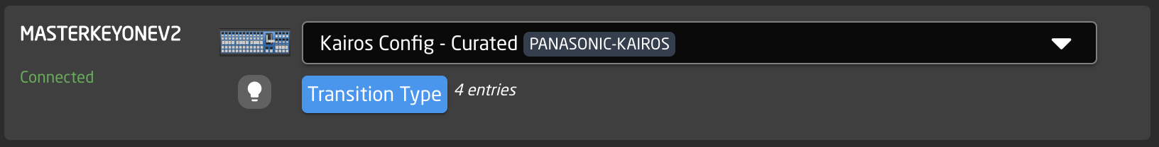
Transition Types
The Transition Types constant set is used with the Panasonic Kairos curated configuration to set the 4 available transitions type buttons.

|
Column |
Description |
|
Order |
Allows for quick rearranging of channel order. Right clicking on order will allow for deleting the row. |
|
Mute |
Allows for removing access to a specific channel or to leave a blank spot on the panel |
|
Transition Index |
Sets the transition type based on order available in the Kairos Creator, see chart below. |
|
Alternate Label |
Customizable name to appear on the displays. Character limit is determined by size of display and can vary. |
|
|
Delete the row. |
|
|
Duplicates the details of the column. |
|
|
Increments the number in the column by +1. |
There are 82 total defined transitions available
| 0 - Blank | 10- Wipe Box Bottom Right | 20- Barn Door Vertical | 30- PW 2 Blade Horizontal | 40- Wipe Fan Center Top | 50-W Swp Par Vertical | 60- windshield | 70- Rotate Top Right | 80- Squeeze Vertical Center |
| 1 - Mix | 11- Wipe Box Bottom Left | 21- Barn Door Horizontal | 31- PW 4 Blade | 41- WipeFan Center Right | 51- W Swp Par Diagonal | 61- Wipe Snake | 71- Rotate Bottom Right | 81- Squeeze Horizontal Center |
| 2 - Mix via Black | 12- WipeBox Top Center | 22- Barn Door Diagonal Bottom | 32- Swipe Clockwise Top | 42- Wipe Fan Top | 52- W Swp Opp Vertical | 62- Wipe Spiral | 72- Rotate Top Left Reverse | 82- Zoom |
| 3 - Mix Via White | 13- Wipe Box Right Center | 23- Barn Door Diagonal Top | 33- Swipe Clockwise Right | 43- Wipe Fan Right | 53- W Swp Opp Horizontal | 63- Scale | 73- Rotate Bottom Left Reverse | |
| 4 -Wipe Left | 14- Wipe Box Bottom Center | 24- Wipe Circle | 34- Swipe Clockwise Bottom | 44- Wipe Fan Bottom | 54- W Swp Diag Top Left | 64- Push Left | 74- Rotate Top Right Reverse | |
| 5 - Wipe Right | 15 - Wipe Box Left Center | 25- Wipe Star 4 | 35- Swipe Clockwise Left | 45- Wipe Fan Left | 55- W Swp Diag Bottom Left | 65- Push Right | 75- Rotate Bottom Right Reverse | |
| 6 - Wipe Top | 16- Wipe 4 Box In | 26- Wipe Star 5 | 36- Swipe clockwise Top Left | 46- Wipe Fan Out Vertical | 56- Saloon Door Top | 66- Push Up | 76- Squeeze Left | |
| 7- Wipe Bottom | 17- Wipe 4 Box Out | 27- Wipe Star 6 | 37- Swipe Counter clockwise Bottom Left | 47- Wipe Fan Out Horizontal | 57- Saloon Door Left |
67- Push Down |
77- Squeeze Right | |
| 8 - Wipe Box Top Left | 18- Wipe Diagonal Top Left |
28- Wipe Clock |
38- Swipe Clockwise Bottom Right | 48- Wipe Fan In Vertical | 58- Saloon Door Bottom | 68- Rotate Top Left | 78- Squeeze Top | |
| 9 - Wipe Box Top Right | 19- Wipe Diagonal Top Right | 29- PW 2 Blade Vertical | 39- Swipe Counter Clockwise Top Right | 49- Wipe Fan In Horizontal | 59- Saloon Door Right | 69- Rotate Bottom Left | 79- Squeeze Bottom |
Quick Controls
Available on some controllers, Quick Control configs are not actually settings tables, however some of them do open up settings table options.

Quick Class Configuration Table

|
Column |
Description |
|
Order |
Allows for quick rearranging of camera order. Right clicking on drag will allow for deleting the row. |
|
Mute |
Allows for removing access to a specific camera or to leave a blank spot on the panel |
|
Bound Device |
Allows for the selecting of a specific connected configuration |
|
Device ID |
Ties the camera selector to the specific device. This is found in the Devices section. Each device will have a unique device number per device core. This box should auto-populate when a device is selected in binding |
|
Device Name |
Enter the name to be used in the displays for the device selection button. |
|
Description |
Custom description for the configuration |
|
Link Selector |
Selects the needed configuration based on the device being connected. |
|
Constant Sets |
Opens up settings tables depending on the selected Quick Controls Config |
|
|
Delete the row. |
|
|
Duplicates the details of the column. |
|
|
Increments the number in the column by +1. |
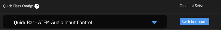
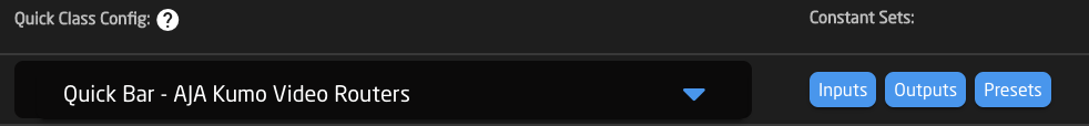
Example of Quick Control Configurations
Quick Class configurations are available for select sections of 6 buttons. These are generally associated with specific devices.

Constant Set Examples
Constant sets tied to quick control can include, but are not limited to, Switcher Inputs, Routing Panels, and Playlists. Please see the settings table example for the option presented with the selected Quick Control Config.