The 3G SDI Arduino Shield imbedded in UniSketch panels is not compatible when using the UniSketch panel with a Blue Pill device. It will only function when working only via the UniSketch platform.
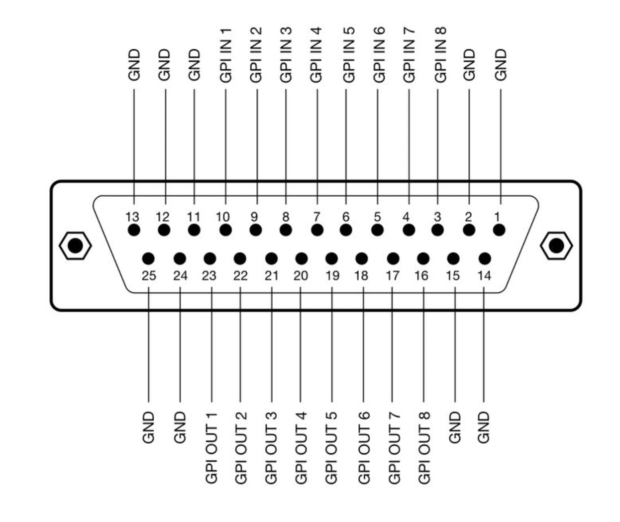
**[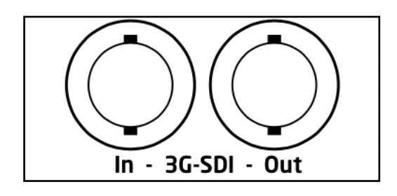](https://wiki.skaarhoj.com/uploads/images/gallery/2022-10/sdi.png)**The Blackmagic 3G-SDI Arduino Shield supports the following formats using SDI Level B: 720p50, 720p59.94, 720p60, 1080i50, 1080i59.94, 1080i60, 1080p23.98, 1080p24, 1080p25, 1080p29.97, 1080p30, 1080p50 (output only), 1080p59.94 (output only) and 1080p60 (output only), but the camera does not have to be running the same video format as the program input, so you can use cameras in Ultra HD while the camera protocol is sent over HD signal to the camera. **Eth-GPI Link and Color Fly DB-25 Connector**The Eth-GPI Link and Color Fly have 8x GPI Inputs and 8x GPI Outputs, this is different than the SDI-GPI Link.
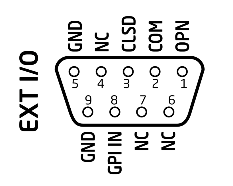
**[](https://wiki.skaarhoj.com/uploads/images/gallery/2022-10/eth-gpi.png)** **RCP v2 DB-9 Connector**The RCPv2 only has 1x GPI Input that is programmable, this is different than the RCP Pro.
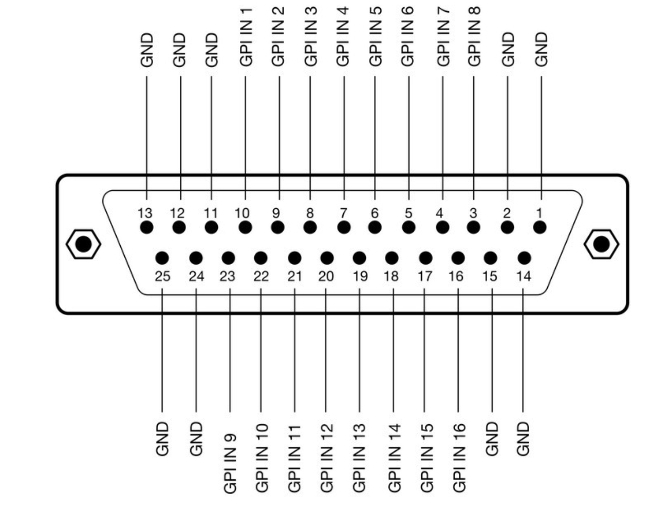
**[](https://wiki.skaarhoj.com/uploads/images/gallery/2022-10/db-9-rcpv2.png)** **SDI-GPI Link DB-25 Connector**The SDI-GPI Link has 16x GPI Inputs and 0x GPI Outputs, this is different than the Eth-GPI Link.
**[](https://wiki.skaarhoj.com/uploads/images/gallery/2022-10/sdi-gpi.png)** **Tally Box and Lights** The pinout of the RJ-45 connector is as follows: 1\. GND 2\. 12V 3\. 5V control signal for red tally 1 4\. 5V control signal for green tally 1 The next four are for daisy-chaining tally lamps: 5\. 5V control signal for red tally 2 6\. 5V control signal for green tally 2 7\. 5V control signal for red tally 3 8\. 5V control signal for green tally 3 Our tally lamps need 12V power in order to light up the LEDs. The control signals are 5V so whenever you apply 5V on one of the pins the corresponding LEDs will illuminate. **[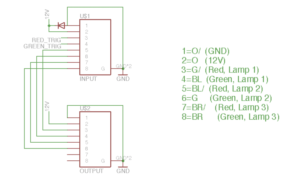](https://wiki.skaarhoj.com/uploads/images/gallery/2022-10/tally-box.png)**