# Device Core Articles
# Introduction to Blue Pill Device Cores
# Understanding Device Core manuals
### Navigating to a Device Manual
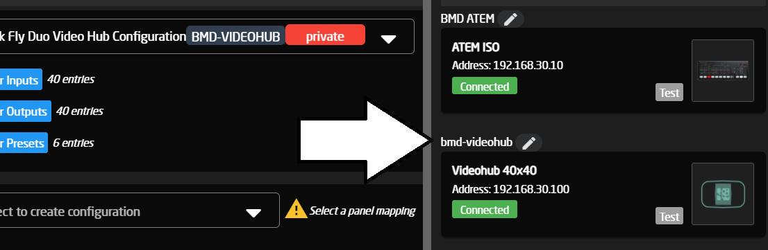
Device cores manuals can be accessed from your Blue Pill in the Device Core options popup.
Click the title above a device you want to know about, to access this popop.
[](https://wiki.skaarhoj.com/uploads/images/gallery/2022-03/image-1646139842274.png)
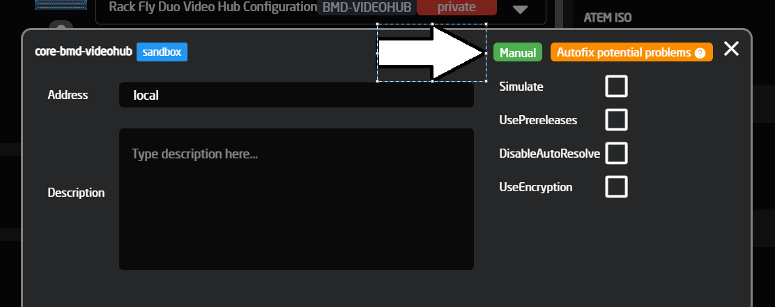
And then click "Manual"
[](https://wiki.skaarhoj.com/uploads/images/gallery/2022-03/image-1646139924925.png)
### How do I use the manual?
The Device core manual is a table view of available and supported parameters of a device core.
[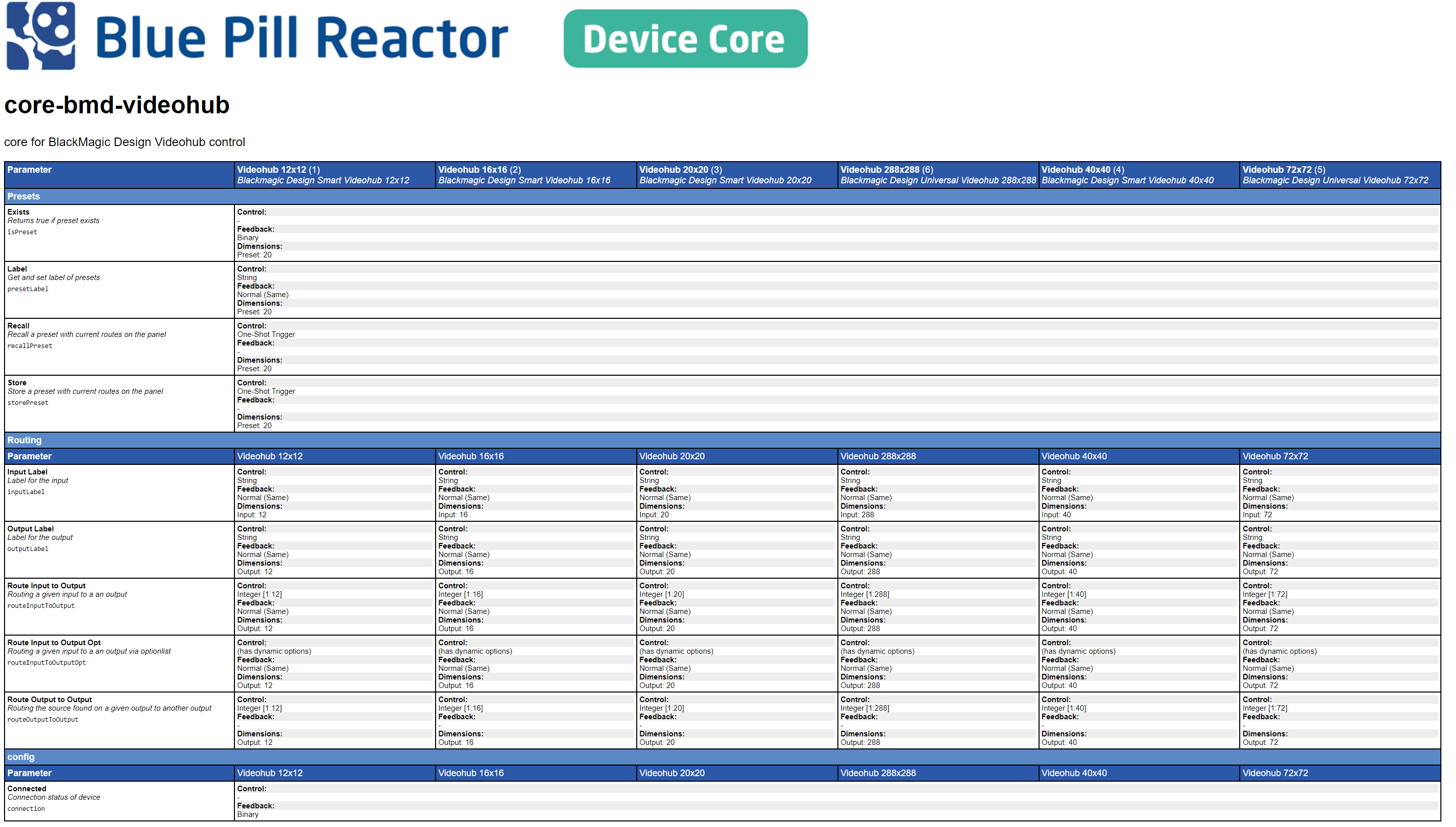](https://wiki.skaarhoj.com/uploads/images/gallery/2022-03/image-1646140040512.png)
*Blackmagic Design - Videohub Device Core Manual example*
On the left side we have listed all available parameters, and in the top row we list all available models.
Then you can find the model that you want to work with and read which parameters are supported for you exact model
# Parameter List- How To
### How to use the parameter list found on devices.skaarhoj.com
In this example our goal is: Determine what parameters can be controlled for the RED Komodo camera
- Go to the website device.skaarhoj.com
- Search for RED or Komodo to find the coremanual with all the parameters
[](https://wiki.skaarhoj.com/uploads/images/gallery/2022-05/image-1651836346288.png)
- Click the "parameter list"
In the new window you can see a table with different columns. The first is Parameter, and contains the specific functions that can be controlled in this core. The next columns is for models supported in this devicecore. In our instance its 2 different cameras, the Komodo and V-Raptor.
- - If you want to see how Skaarhoj supports *color temperature*, you would simply scroll down the list and find the parameter. [](https://wiki.skaarhoj.com/uploads/images/gallery/2022-05/image-1651837327379.png)
[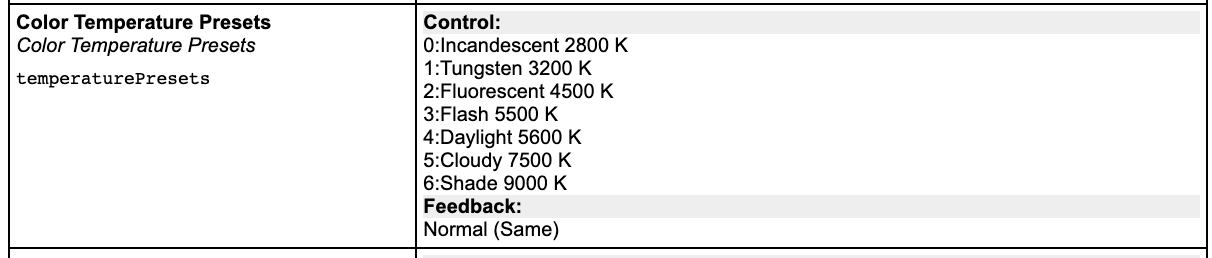](https://wiki.skaarhoj.com/uploads/images/gallery/2022-05/image-1651837289846.png)
- These names is the exact names you will get in your display on a Skaarhoj Panel
Note: In this example information about color temperature is handle the same across the two camera models
- - We can also take a look at the parameter for contrast. Here the two cameras have different ways of handling this information [](https://wiki.skaarhoj.com/uploads/images/gallery/2022-05/image-1651837331770.png)[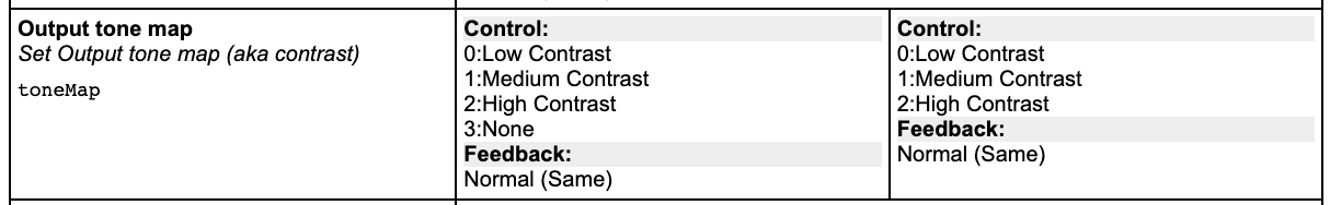](https://wiki.skaarhoj.com/uploads/images/gallery/2022-05/image-1651837306747.png)
These parameter list are related to the version of the devicecore you are running. So when troubleshooting please be aware of what verison of the device core you are running. (Information about the version is located on the top of the page)
[](https://wiki.skaarhoj.com/uploads/images/gallery/2022-05/image-1651837826554.png)
# AJA FrameSync Video Channels
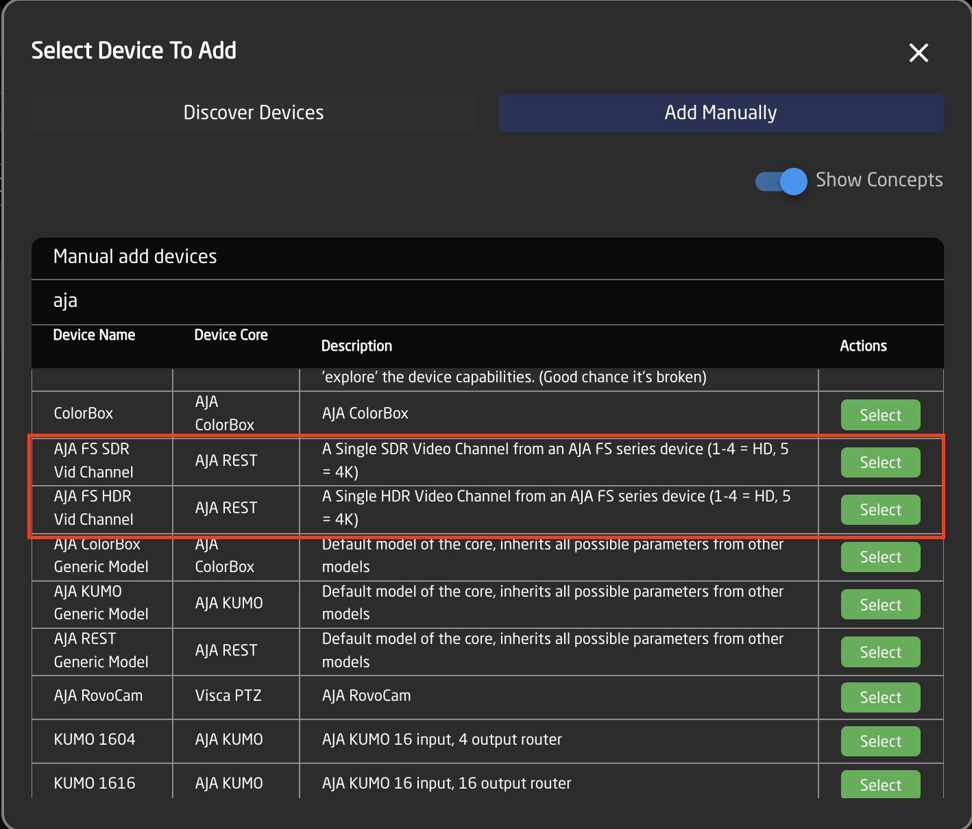
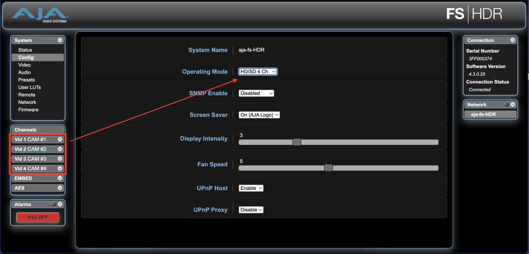
When controlling individual video channels of an AJA FS series frame sync, it is important to add the video channel as an individual device. Selecting AJA FS SDR or AJA FS HDR Vid Channel depending on your FS model.
[](https://wiki.skaarhoj.com/uploads/images/gallery/2025-10/screenshot-2025-10-29-at-14-51-21.png)
After adding the Vid Channel as a device, input the IP address for the FrameSync and specify which channel is being controlled in the Camera ID field.
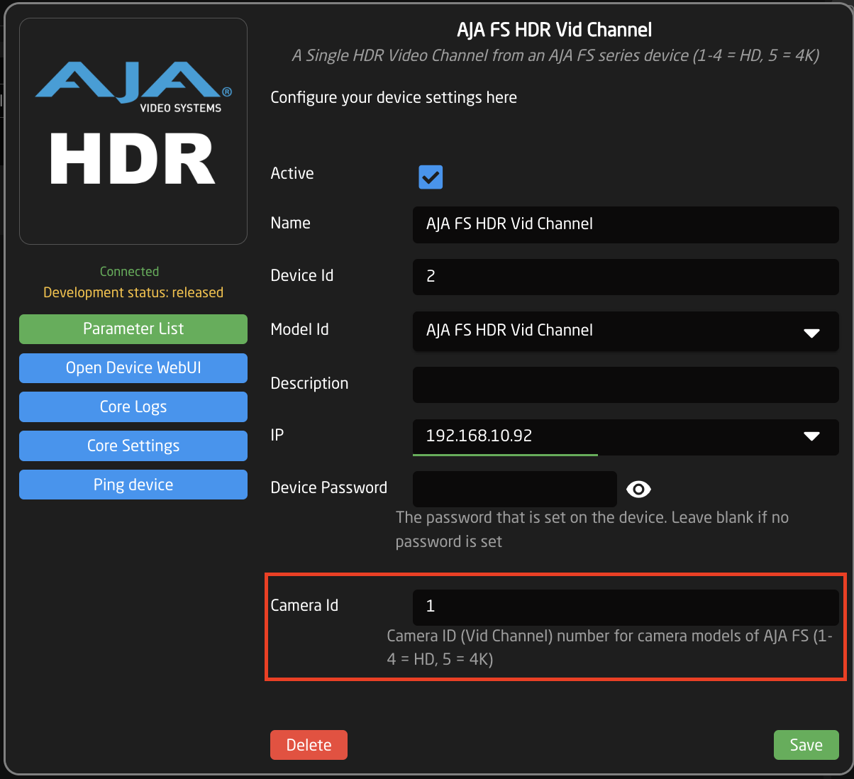
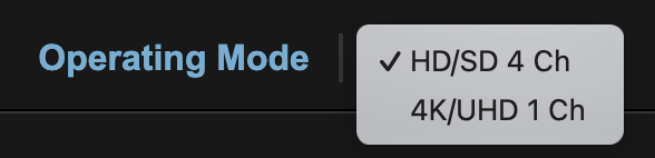
IDs 1-4 correspond to Vid Channels 1-4 when when in HD/SD mode as defined in the Operating Mode within the FS web interface.
[](https://wiki.skaarhoj.com/uploads/images/gallery/2025-10/screenshot-2025-10-29-at-14-56-18.png)
ID 5 corresponds to the single 4k channel when Operating Mode is set to 4k/UHD within the AJA Frame Sync web interface.
[](https://wiki.skaarhoj.com/uploads/images/gallery/2025-10/screenshot-2025-10-29-at-15-06-13.png)
# Arri Camera settings
The SKAARHOJ Arri device core can control Arri Cameras over CAP and older cameras over SSCP.
Please make sure to adjust the settings in the camera(s).
####
Arri Amira & Arri Alexa Mini
\- Enable CAP in the menu
\- Use Arri Multicam Look file, otherwise you might not be able to change color parameters
\- Enable Multicam Mode, set SSCP IP to the IP of your SKAARHOJ Panel
#### Arri Alexa Mini LF
This camera only supports CAP, which makes setup easier
\- Enable CAP in the menu, check the set password (default: arri)
\- Use Arri Multicam Look file, otherwise you might not be able to change color parameters
\- Enable Multicam Mode, set SSCP IP to the IP of your SKAARHOJ Panel
#### Arri Alexa35
This camera only supports CAP, which makes setup easier
\- Enable CAP in the menu, check the set password (default: arri)
\- Make sure your camera is fully up to date and has the Arri Multicam License
\- Turn on Live Painting in the menu
\- Duplicate the default Look File, otherwise you might not be able to change color parameters
# Biamp Tesira
The Biamp Tesira core has two different models, the Manual model and the Auto model.
#### Manual Model
The manual model works well for very simple setups, that only needs control of a few parameters. It requires a little more setup, but will not use as many resources on the Blue Pill.
#### Auto Model
The auto model works by automatically reading the config running on the Tesira, and configuring the controllable parameters to fit them. This is the easiest model in most cases, and is also the one working with [AudioClass configs](https://wiki.skaarhoj.com/books/blue-pill-reactor/page/audio-class-configuration).
#### Setup
Manual Model
This is a guide on how to connect and control a Biamp Tesira audio processor. Since the Biamp Tesira uses 'Block names' and 'Channel numbers inside a block' there is an extra setup-layer involved, compared to other devices.
Please note: This guide covers the '**Manual Tesira**' model.
#### Add device
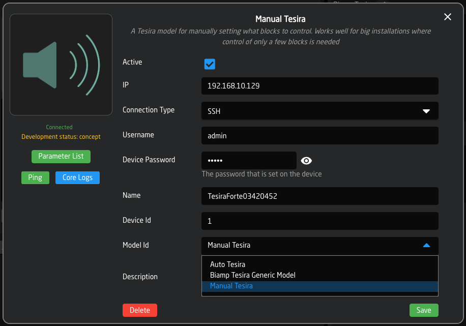
On Reactor > Home page you click 'Add Device' to open the devices list. Tesira can by auto discovered. If you don't see the Tesira, you may have to go to the 'Packages' page and manually install the 'core-biamp-tesira' package.
When adding the Tesira, please select the Model Id : Manual Tesira.
[](https://wiki.skaarhoj.com/uploads/images/gallery/2023-12/Vf6image.png)
#### Create custom configuration
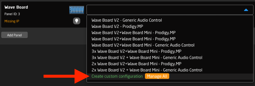
We have not yet made any default configurations for the Biamp Tesira. This means you must make your own configuration to assign commands to buttons/faders/etc.
Next to your device icon, open the Configuration pop-up menu and select 'Create custom configuration'. Give it a name and click 'Create'.
[](https://wiki.skaarhoj.com/uploads/images/gallery/2023-10/custom-config.png)
#### Control using 'Dimensions'
Biamp Tesira is a very flexible audio processor. Instead of just having fixed 'channel numbers' you have both 'Block names' and 'Channel number within a block'. Because of this we need an extra layer to point towards the desired control. We call these 'Dimensions'.
A 'Dimension' is a number, which is linked to a 'Block name' and a 'Channel number'.
For example, we can specify:
- Block name 'Level3' = Dimension 1
- Channel number 1 = Dimension 1
Then we can send the command:
- Level \[Dimension 1\] = -10dB
The actual commands are:
- Specify 'block' in Dimension 1
parameter: DC:biamp-tesira/1/Level\_Instance\_Str/1/
behavior: set value directly
value: "Level3"
- Specify 'channel' in Dimension 1
parameter: DC:biamp-tesira/1/Level\_Channel/1/
behavior: set value directly
value: 1
- Change level on Dimension 1
parameter: DC:biamp-tesira/1/S\_Level\_level/1/
behavior: set value directly (or use StepChange)
value: -10db
You can send all 3 commands in a row from a button using a 'Multi behavior'.
[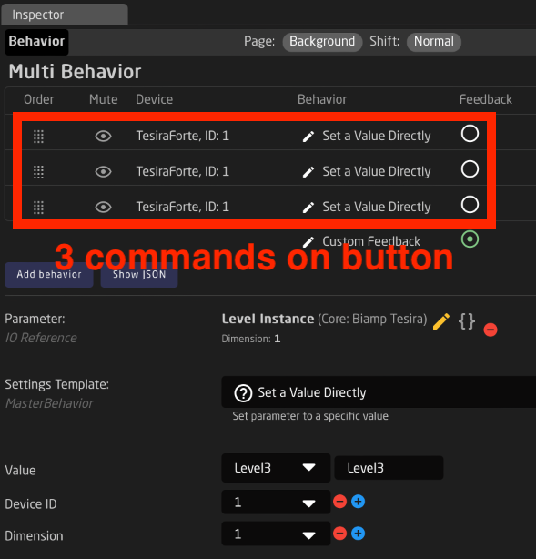](https://wiki.skaarhoj.com/uploads/images/gallery/2023-10/multi-behavior.png)
**NOTE**: You only need to specify Dimensions once until you reboot the controller. (You can avoid having 3 commands on every button by using Virtual Triggers to setup the dimension at startup - see below.)
**NOTE**: Depending on the block, the Dimension will include different parameters. Fx. a 'Level Block' includes; Level, Mute, and Label. Other blocks include other parameters.
#### Dimension count
By default there are 25 Dimensions available for each block type. This can be changed in: Home page > click Biamp Tesira device core name to open its settings > Edit 'Manual dimension count'
[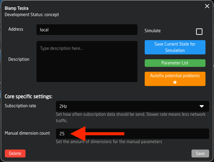](https://wiki.skaarhoj.com/uploads/images/gallery/2023-12/dp0image.png)
#### Use Virtual Triggers for Dimension setup
Instead of sending 3 commands from each button, you can pre-configure all 'Dimensions' using Virtual Triggers. This way you specify the link between 'Block name', 'Channel number' and 'Dimension number' once at startup. After this, when sending commands you just use one command that includes the 'Dimension number'.
Example of Virtual Trigger that defines 4 dimensions (4 channels in the same block):
IF: At startup and Tesira is connected
THEN:
- Block name 'Level3' = Dimension 1
- Channel number 1 = Dimension 1
- Block name 'Level3' = Dimension 2
- Channel number 2 = Dimension 2
- Block name 'Level3' = Dimension 3
- Channel number 3 = Dimension 3
- Block name 'Level3' = Dimension 4
- Channel number 4 = Dimension 4
After this you only need to send one command from buttons/faders. For example:
- Level \[Dimension 1\] = -10dB
- Level \[Dimension 2\] = 0dB
- Mute \[Dimension 3\] = On
'IF' screenshot:
[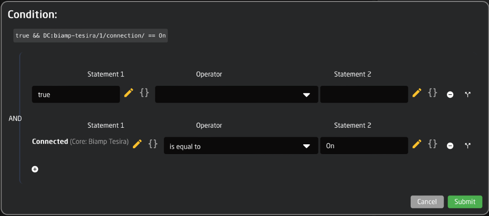](https://wiki.skaarhoj.com/uploads/images/gallery/2023-10/Szrif.png)
'THEN' screenshot (using one Event Handler with 'Binary > Sequence'):
[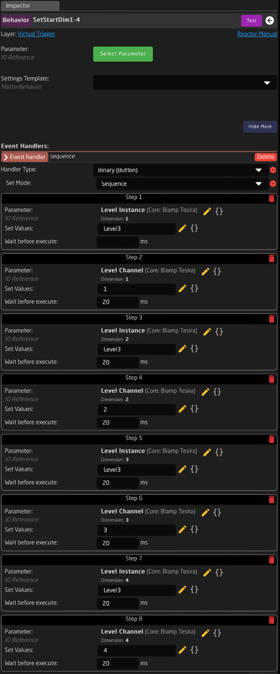](https://wiki.skaarhoj.com/uploads/images/gallery/2023-10/gpNthen.png)
Auto Model
#### Add device
On Reactor > Home page you click 'Add Device' to open the devices list. Tesira can by auto discovered. If you don't see the Tesira, you may have to go to the 'Packages' page and manually install the 'core-biamp-tesira' package.
When adding the Tesira, please select the Model Id : Auto Tesira.
[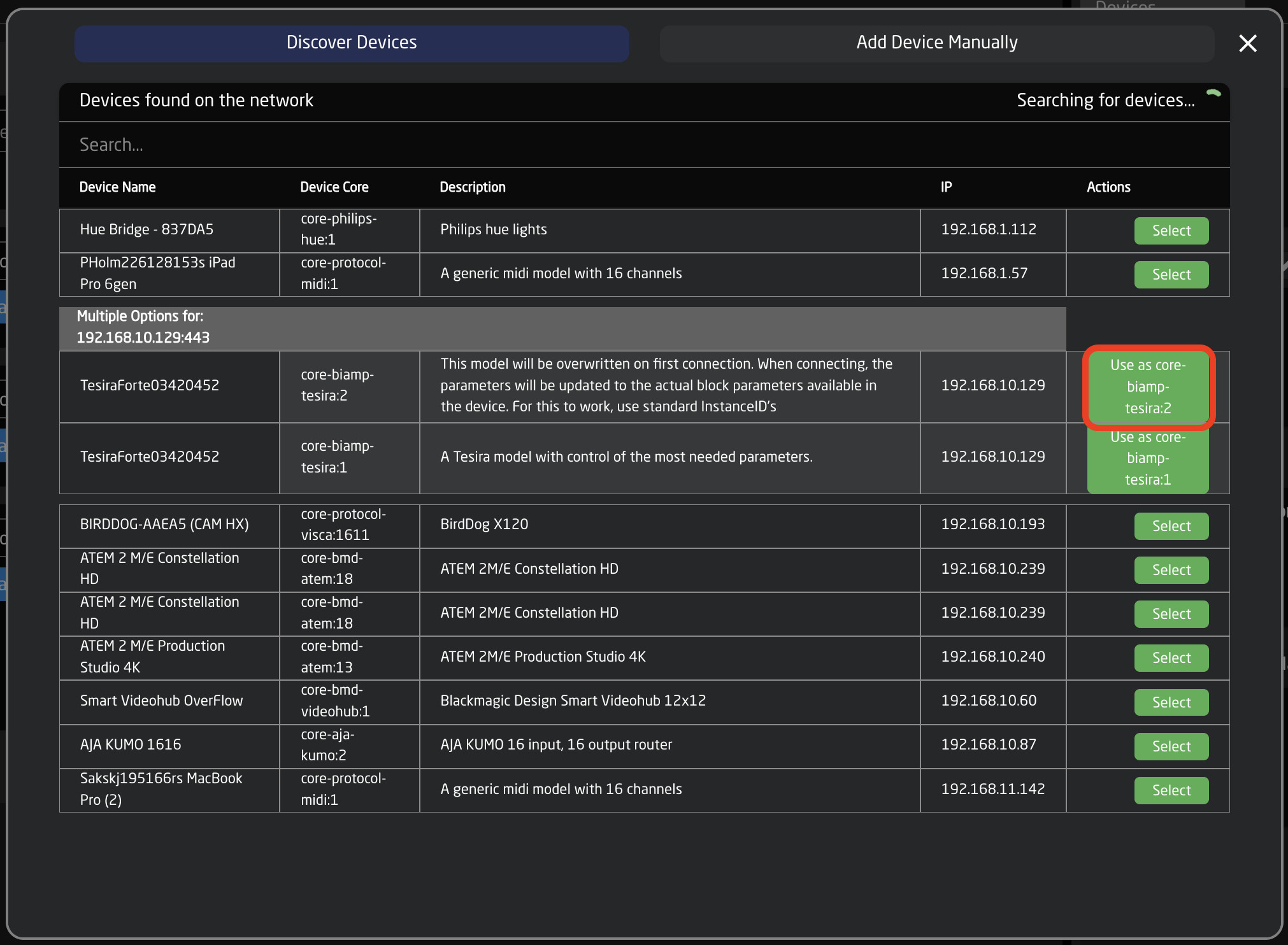](https://wiki.skaarhoj.com/uploads/images/gallery/2023-12/RUyimage.png)
When the device has been added, the device config can be opened by clicking the name.
Here you would find the following settings. Remember to set username and password here.
The first time you connect, the 'Regenerate auto' should be enabled. This reads the config from the Tesira, and generates the parameters needed.
[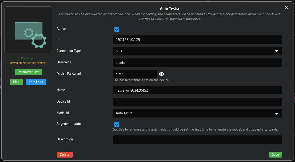](https://wiki.skaarhoj.com/uploads/images/gallery/2023-12/bs6image.png)
When the device states 'Connected', the [Parameter List](https://wiki.skaarhoj.com/books/blue-pill-reactor/chapter/device-core-parameter-lists "Device Core Parameter Lists") can be opened and reviewed. It is grouped into the different block types, and shows what parameters can be controlled on each block type.
Each parameter should show some different dimensions. The first specifying the Instance Id of that dimension, and the second and possibly third specifies the channel, inputs or outputs available for control.
[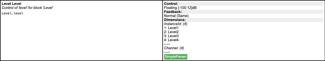](https://wiki.skaarhoj.com/uploads/images/gallery/2023-12/i12image.png)
This is an example of a parameter in the Parameter List. The left side has the label, description and name. The right side shows the control and feedback of of the parameter, and the dimensions described above.
In this case, we see 4 level blocks, with 4 channels each. Each block might not have 4 channels, but that number is set to the block with the highest channel count.
Now you are ready to either add channels to an Audio Class config, or start your own configuration from scratch.
# BirdDog Cameras
All Blue Pill integrations for the BirdDog cameras have been made using their NDI 5 firmwares.
**SHUTTER VALUES**
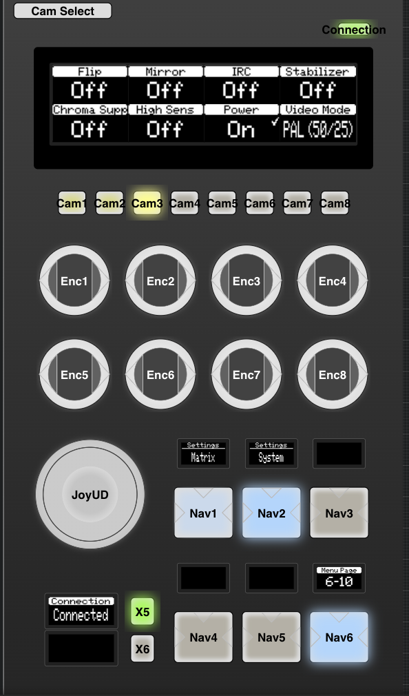
The shutter values on the BirdDog camera are different depending on which video format you are using. The camera does not make it known to the Skaarhoj panel which value range is needed. To solve this, there is a Video Mode parameter that will allow you to tell the panel if you are using NTSC or PAL value ranges.
Video Mode is available starting with Core-Protocol-Visca v0.2.7 on the packages page.
[](https://wiki.skaarhoj.com/uploads/images/gallery/2023-06/screenshot-2023-06-20-at-09-14-59.png)
This value may need to be reset after camera or panel reboot.
**MAPPING**
By default, the Video Mode parameter is available in the Visca-BirdDog Pro Class configuration for PTZ Extreme and RCP Pro/RCPv2 on the System Page.
Video Mode was added to the default configuration with Reactor v1.0.8-pre1 on the packages page.
For other configurations or when using Visca-AllStars configuration it is necessary to add the parameter to the menu you desire.
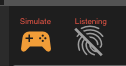
The quickest way to map the parameter would be to go to the Configuration Page, then put the Controller Section into either Simulation Mode which allows you to control the panel from the screen or in Listening Mode which allows you to press buttons on your physical panel to control which HWC you want to edit.
[](https://wiki.skaarhoj.com/uploads/images/gallery/2023-06/screenshot-2023-06-20-at-09-33-26.png)
[](https://wiki.skaarhoj.com/uploads/images/gallery/2023-06/screenshot-2023-06-20-at-09-32-55.png)
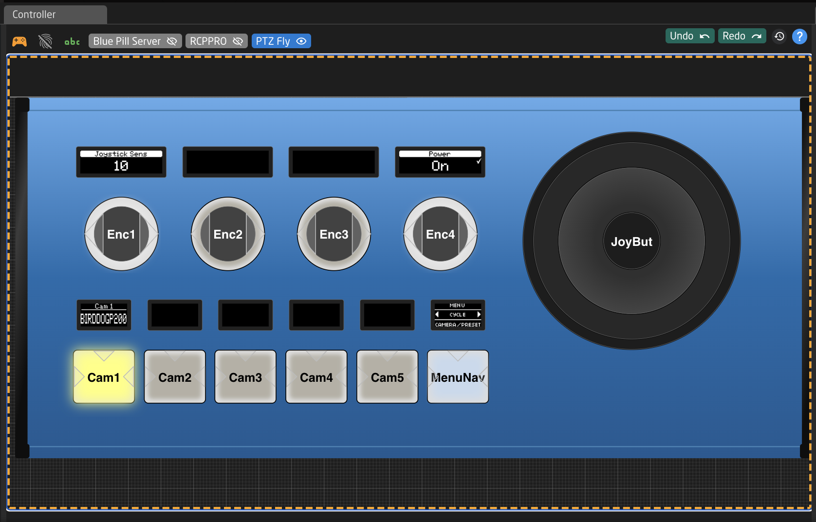
Using either method, navigate to the specific spot you want to map the parameter. In the example below I have selected Encoder 3 in the Various layer.
[](https://wiki.skaarhoj.com/uploads/images/gallery/2023-06/xPfscreenshot-2023-06-20-at-09-37-50.png)
In the Inspector section, click Edit above the Parameter you are either replacing or if blank, where you are adding.
This will open the editor.
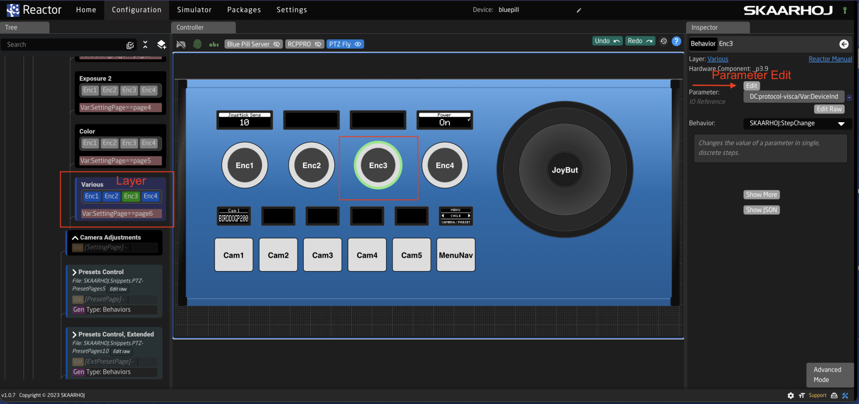
Since this change should effect any BirdDog cameras on the panel, select the Select Core (Advanced) option and not a specific camera. If you are mixing different brands of visca cameras, note that this change would effect those as well.
[](https://wiki.skaarhoj.com/uploads/images/gallery/2023-06/screenshot-2023-06-20-at-09-42-11.png)
To make sure the parameter is following the camera select, when using our default configurations, the first set up drop downs should tie the parameter to the Variable: DeviceIndex. These options should be available in the marked drop downs.
[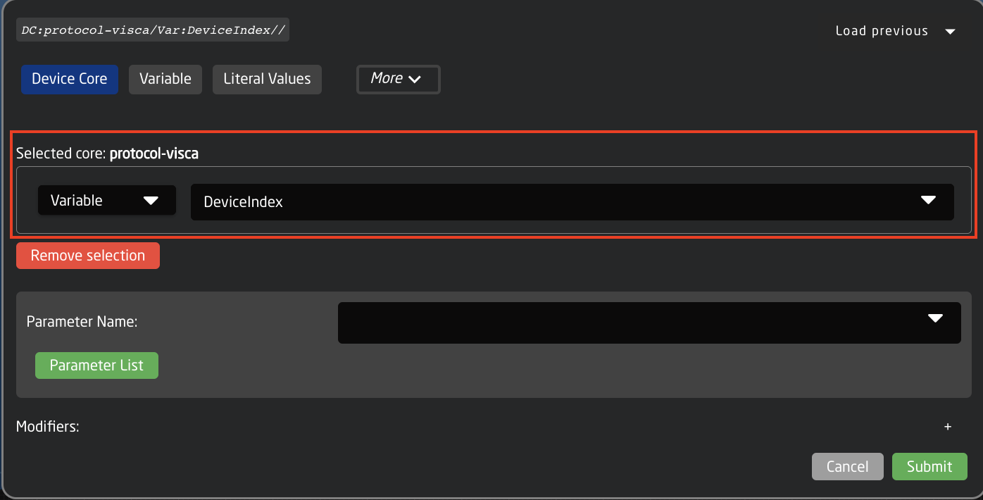](https://wiki.skaarhoj.com/uploads/images/gallery/2023-06/screenshot-2023-06-20-at-09-45-55.png)
Next select the correct parameter in the Parameter Name field. Please note that as the visca core is designed for a large number of cameras, some parameters may have similar names. It is possible to double check which is the correct parameter for your model of camera in the [Parameter List ](https://cloud.skaarhoj.com/coremanual/core-protocol-visca)
[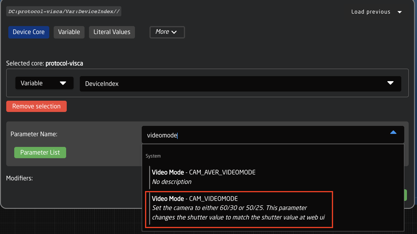](https://wiki.skaarhoj.com/uploads/images/gallery/2023-06/screenshot-2023-06-20-at-09-47-54.png)
Once the correct parameter has been selected, press Submit.
It is also necessary to select the correct Behavior (prebuilt definition of how the hardware component should act). In this instance it should be StepChange, meaning it will step through the various options available.
[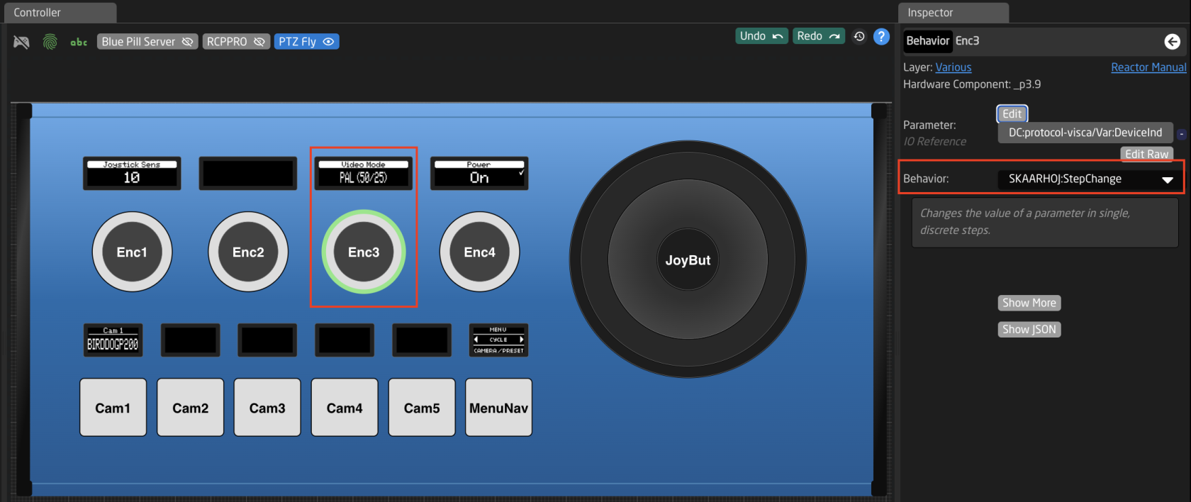](https://wiki.skaarhoj.com/uploads/images/gallery/2023-06/ATFscreenshot-2023-06-20-at-09-51-38.png)
The parameter should then appear on the panel in the place it was set and be ready to test. If it does not, try restarting the Reactor package on the Packages Page. Or double check it was place in the correct spot.
# Blackmagic Camera Control via Atem
It is possible to control your Blackmagic cameras through an Atem switcher using your Skaarhoj Blue Pill panel.
1. Make sure you are have installed the BMD Atem device core package v0.0.6-pre21 or later. You can see what version you are currently using on the Packages page. [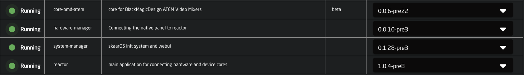](https://wiki.skaarhoj.com/uploads/images/gallery/2022-10/packages.png)
2. Add an instance of your Atem switcher on the Home Page under Devices and input its IP address on your network.
Please note: If you are using an Atem Constellation 8K in 4K mode, you need to select the Atem Constellation 4K to make sure all the correct settings are applied. If you are using it in 8K mode, select the Atem Constellation 8K.
[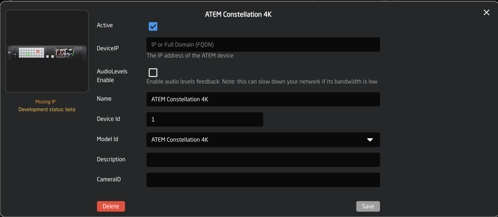](https://wiki.skaarhoj.com/uploads/images/gallery/2022-10/add-atem.png)
3. Using manual discovery, add your BMD cameras. Make sure you select the model that uses the BMD Atem device core NOT the BMD Cam Control device core.
Tip: Holding down the shift button on your keyboard while clicking Select will allow you to select multiple cameras.
[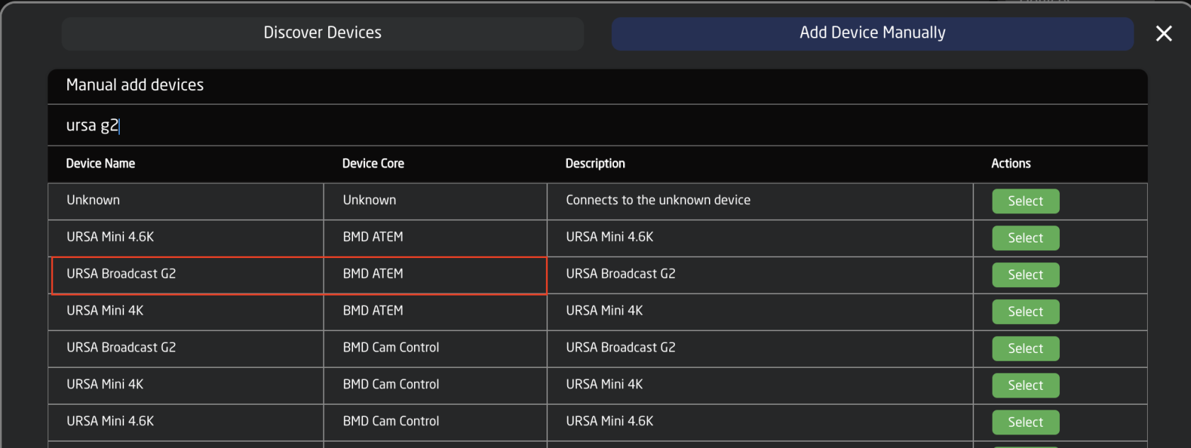](https://wiki.skaarhoj.com/uploads/images/gallery/2022-10/use-bmd-atem-core.png)
4. In the device details for each camera enter the IP address of the Atem switcher and the camera/input number for each camera. [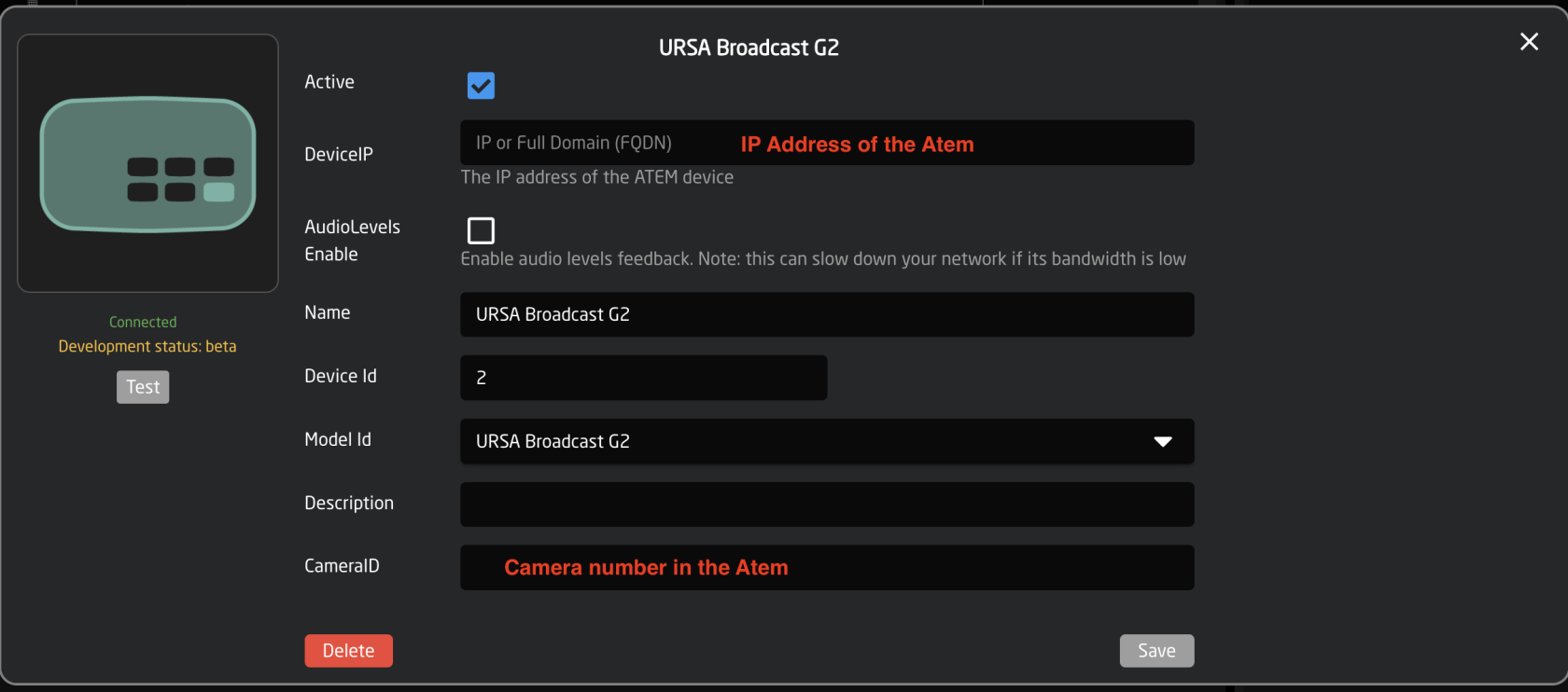](https://wiki.skaarhoj.com/uploads/images/gallery/2022-10/device-details.png)
5. Select the Generic PTZ Control configuration in the config drop down for your panel.
Please Note: The Generic PTZ Configuration is available on a large number of controllers. Using this configuration allows for the easy addition and set up of multiple models and brands of cameras. The configuration will be custom to each camera type.
[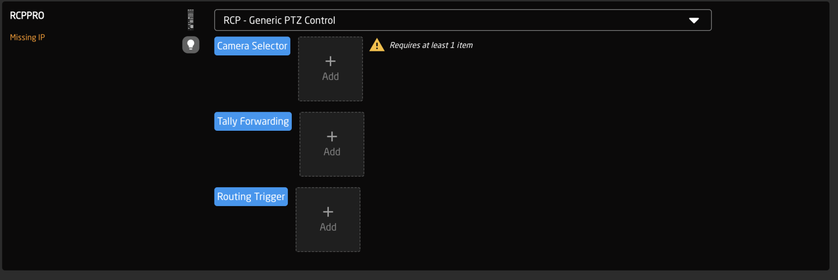](https://wiki.skaarhoj.com/uploads/images/gallery/2022-10/use-generic.png)
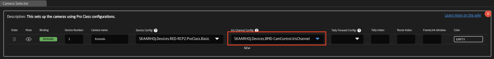
6. Add your cameras to the camera selector double checking that the Device Config and Iris Chanel Config drop downs have the BMD ATEM CamControl selected.
Please Note: There are some use cases that would use a different Iris Channel Config, but for all lenses that are controlable via the camera this is the correct selection.
[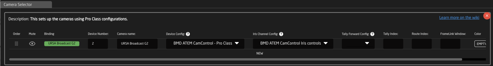](https://wiki.skaarhoj.com/uploads/images/gallery/2022-10/check-config-slots.png)
7. Success! You should be ready to start shading your BMD cameras from your Skaarhoj panel.
# Blackmagic Camera Control via Rest API
Firstly you need to download and install Blackmagic Camera Setup program from here [https://www.blackmagicdesign.com/support/family/professional-cameras](https://www.blackmagicdesign.com/support/family/professional-cameras)
in Blackmagic Camera Setup you need to select these checkboxes for able to control the camera throw the REST API
[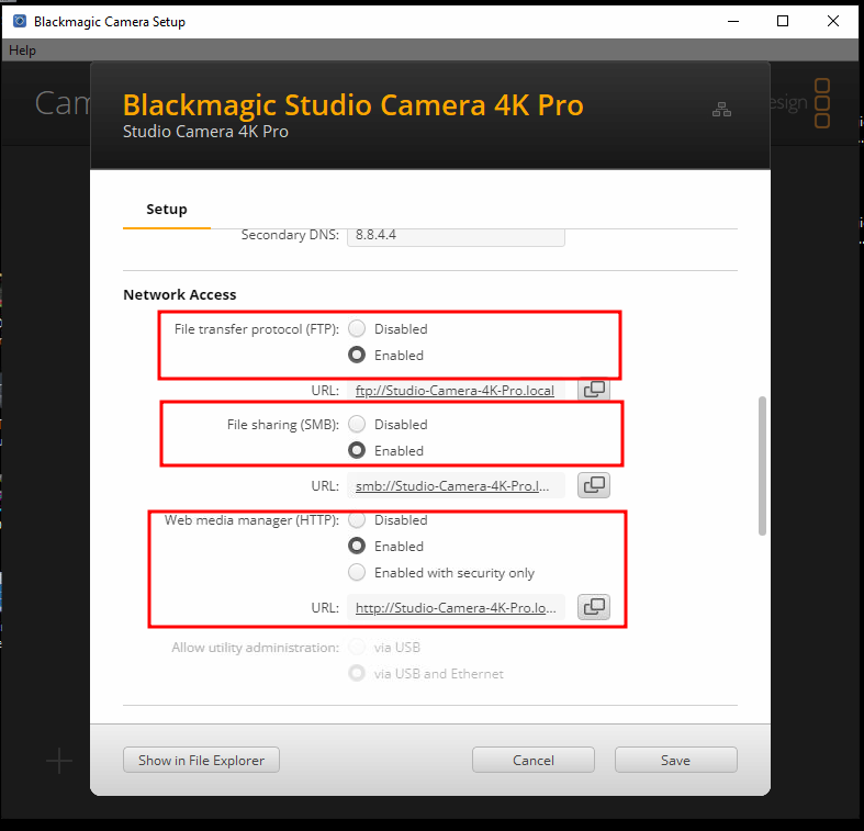](https://wiki.skaarhoj.com/uploads/images/gallery/2024-01/0Y0image.png)
*Note for "REST Camera Control" you only need to have the "Web Media Manager" enabled, the other 2 are more nice to have if you want to use the camera with Davinci Resolve for remote file managing*
# Canon EOS C500 and EOS C300 (Canon-XC)
The currently recomended Core version for EOS C500 and EOS C300 is depended on the firmware version your cameras is on.
This matrix should explain what Canon-XC core version as appropriate for your camera:
Canon XC Core Version
Device Core v0.1.9 or below
Device Core v0.2.0-Pre3 or above
Canon EOS C300 Mark III
Canon Firmware v1.0.3.1 or below
Canon Firmware v1.0.4.1 or above
Canon EOS C500 Mark II
Canon Firmware v1.0.5.1 or below
Canon Firmware v1.0.6.1 or above
If you do not have the newest firmware and want to update your cameras, then you can find the firmware for both models on the Canon USA website by following these links:
[EOS C300 Mark iii](https://www.usa.canon.com/support/p/eos-c300-mark-iii)
[EOS C500 Mark ii](https://www.usa.canon.com/support/p/eos-c500-mark-ii)
# Clear-Com Station-IC
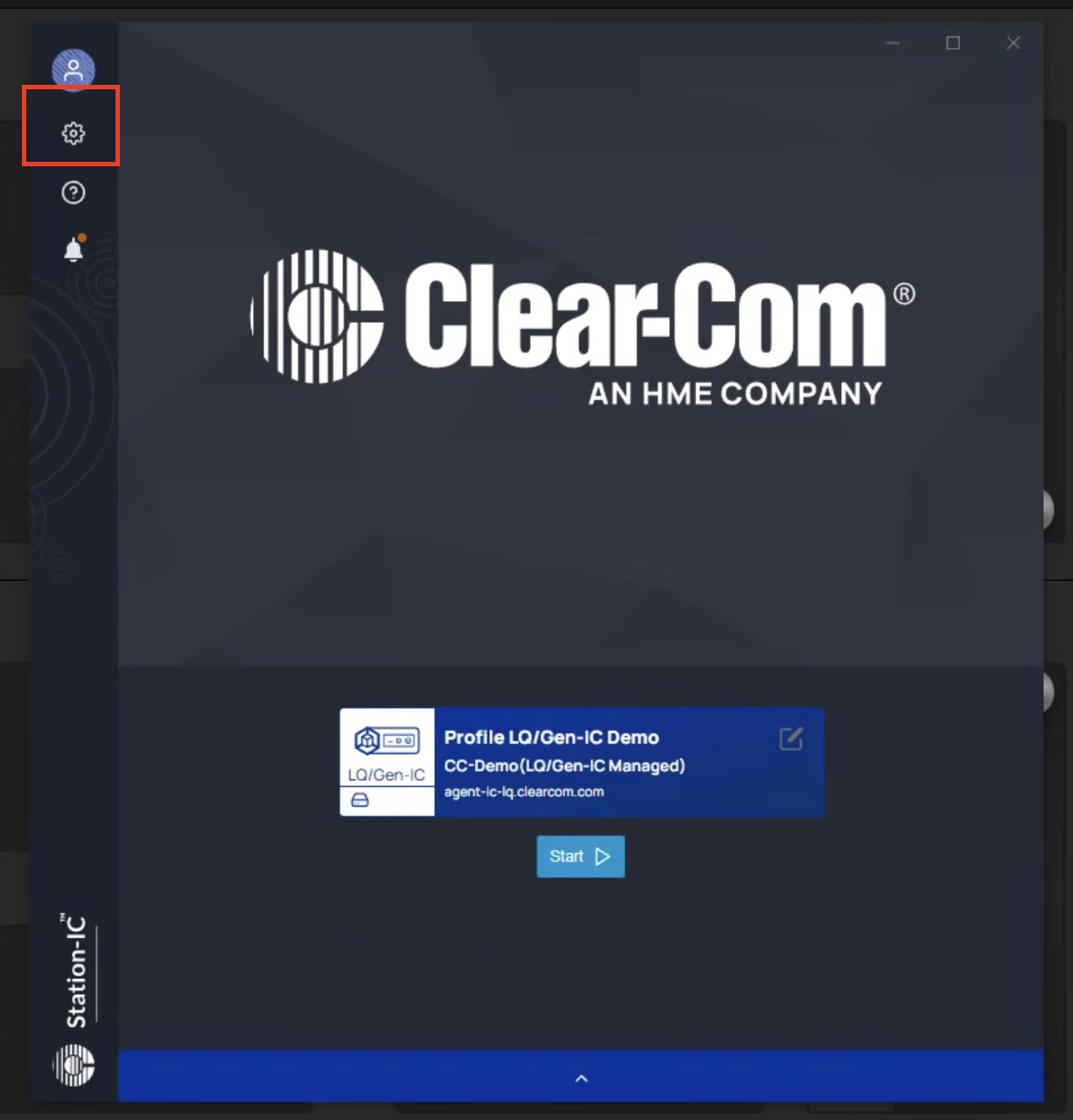
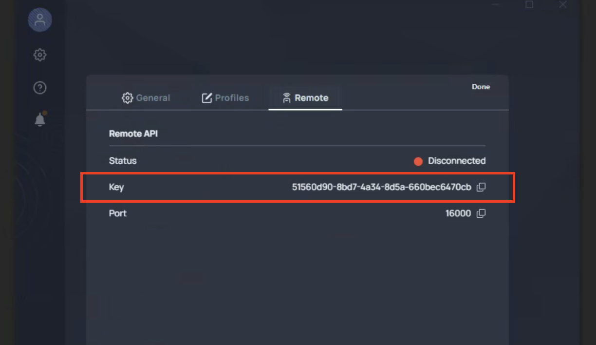
To connect the device core to Clear-Com, you need a Clear-Com Station IC client installed on your PC and copy the Api Key, which can be found on Settings/Remote/Key, to the Device core settings (see pictures below)
[](https://wiki.skaarhoj.com/uploads/images/gallery/2025-09/f90image.png)
[](https://wiki.skaarhoj.com/uploads/images/gallery/2025-09/X00image.png)
# DataVideo PTR-10 and PTC-150
Some DataVideo devices only support their proprietary DVIP protocol over the network. For connection and control using the Visca protocol from a Skaarhoj panel, an ethernet to serial converter can be used.
**Ethernet to Serial connection**
To communicate via serial (RS-485) to the camera you need an Ethernet-Serial converter. We suggest you get a TCP232-306 from USR- [https://www.usriot.com/products/serial-to-ethernet-server.html ](https://www.usriot.com/products/serial-to-ethernet-server.html)
The TCP232-306 is not the only ethernet to serial converter that works, but is the model we tested in house with the DataVideo devices.
Below you will find screenshots of how to configure the USR-TCP232-306 converter (found on the web interface of the TCP232-306). Notice the IP address of the TCP232-306 (Static IP Address) must match the IP settings of the Datavideo PTC-150 Device Core.
**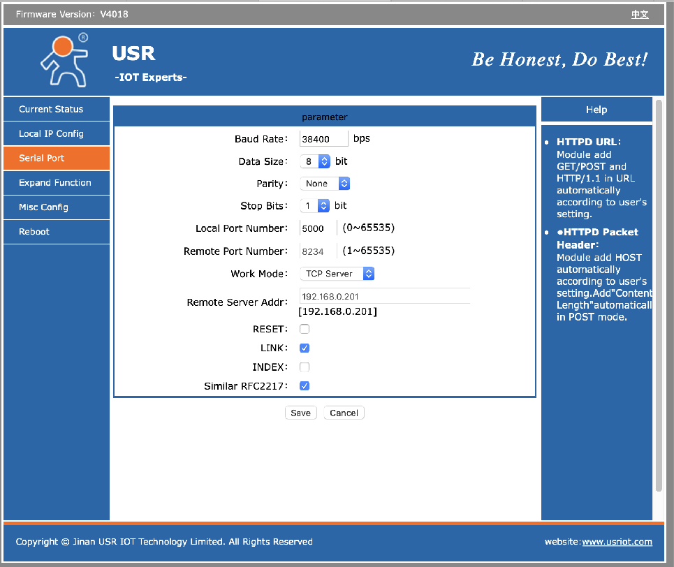**
The specific Baud Rate used is set in the Camera’s OSD.
**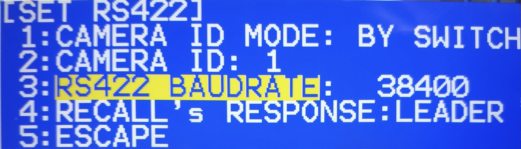**
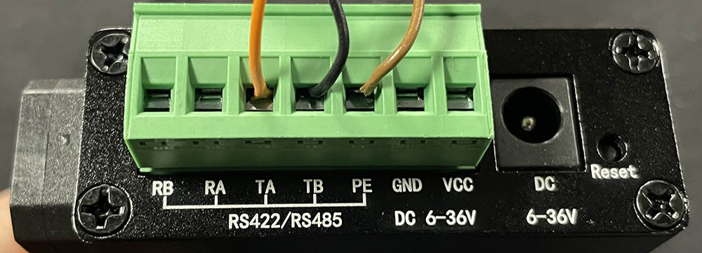
Wiring to the Camera/Converter
**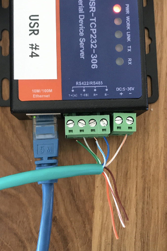**
**Serial Converter**
**RJ45**
**GND**
**White/Orange**
**Rx-**
**Blue**
**Rx+**
**White/Blue**
**Tx-**
**White/Green**
**TX+**
**Green**
**Dip Switches**
On PT Head dip switch settings.
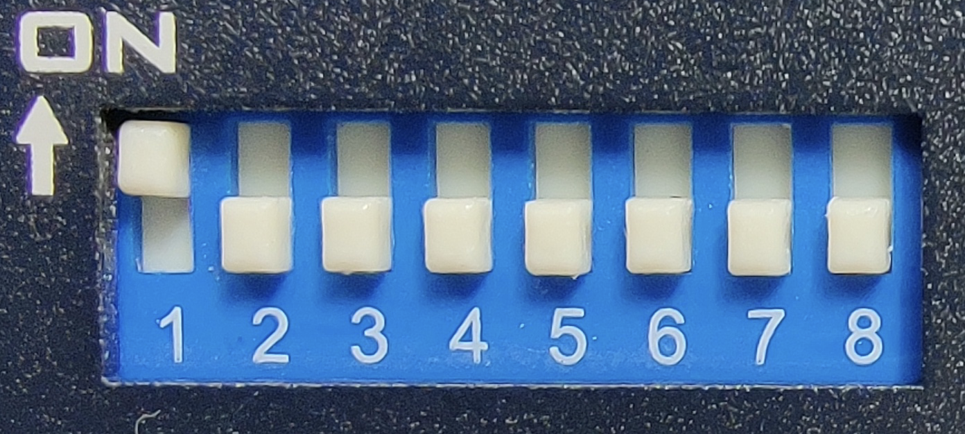
Function
Switch
On/Off
Visca-ID 1
1
On
Visca-ID 2
2
Off
Visca-ID 3
3
Off
Remote Control Protocol
4
Off for RS-422
Video Resolution
5-7
See Camera manual for desired resolution
Video Mode Selection Method
8
Off
See the Datavideo PTR-10 /PTC-150 Instruction Manual for detailed Dip Switch configuration.
# DreamChip Camera Setup and Test
This guide outlines cabling workflows to connect DreamChip cameras to SKAARHOJ-recommended third-party serial converters and test the connection.
[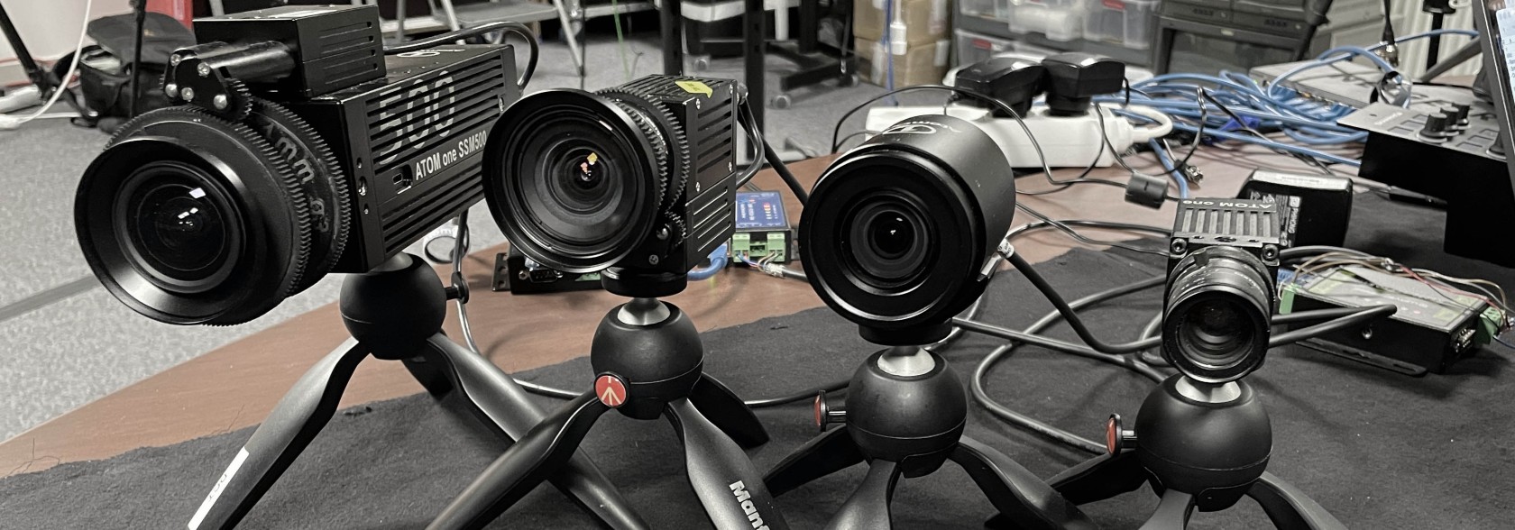](https://wiki.skaarhoj.com/uploads/images/gallery/2023-11/img-8836.JPG)
### Cabling Options for DreamChip Cameras with SKAARHOJ Control
- **Ethernet-Serial Converter:**
- An affordable device connects to your network.
- Forwards DreamChip cameras' RS-485 protocol to a TCP server.
- Use DreamChip's standard cables and an additional Mini-XLR male cable for the serial converter.
- Options:
- a. One converter per camera. (E)
- b. Daisy chain multiple cameras on one converter with different RS-485 addresses (advanced). (D)
- **Direct Web Socket Connection:**
- Exclusively for the SSM500 model, highly recommended. (B)
- **USB-Serial Cable Connection:**
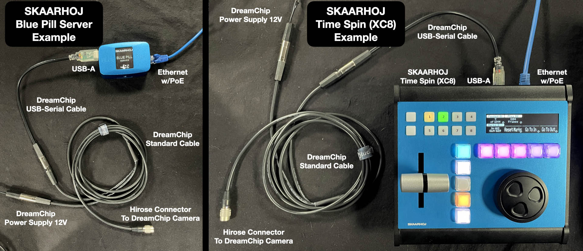
- Connect to SKAARHOJ Blue Pill Server (A) or controllers with USB-A support (e.g., XC8). (C)
- DreamChip provides USB-Serial cables.
[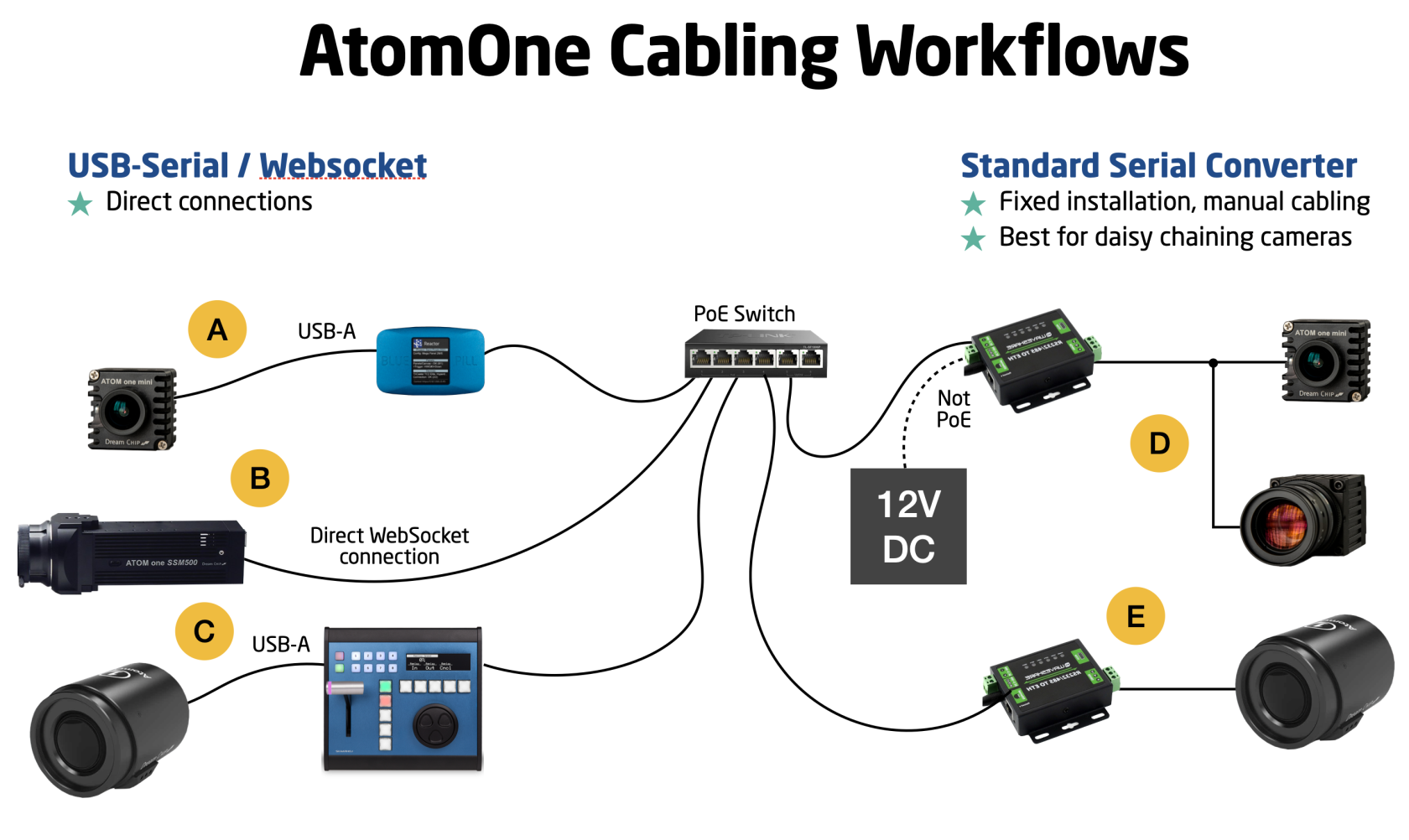](https://wiki.skaarhoj.com/uploads/images/gallery/2023-11/tOLimage.png)
For a workflow involving a DreamChip AtomOne camera mounted on a BR Remote Micro L Pan/Tilt head, we recommend a similar approach:
[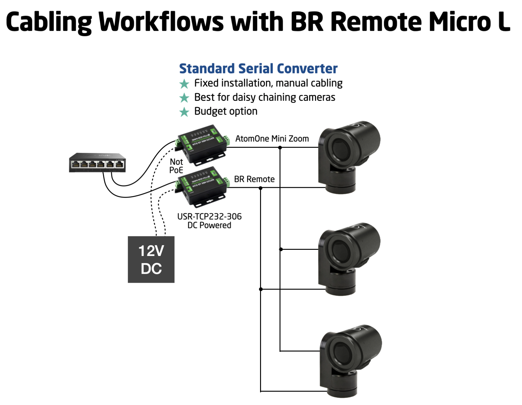](https://wiki.skaarhoj.com/uploads/images/gallery/2023-11/K8Eimage.png)
If you're curious about the proper cabling for a daisy-chained camera setup, this overview should be helpful:
[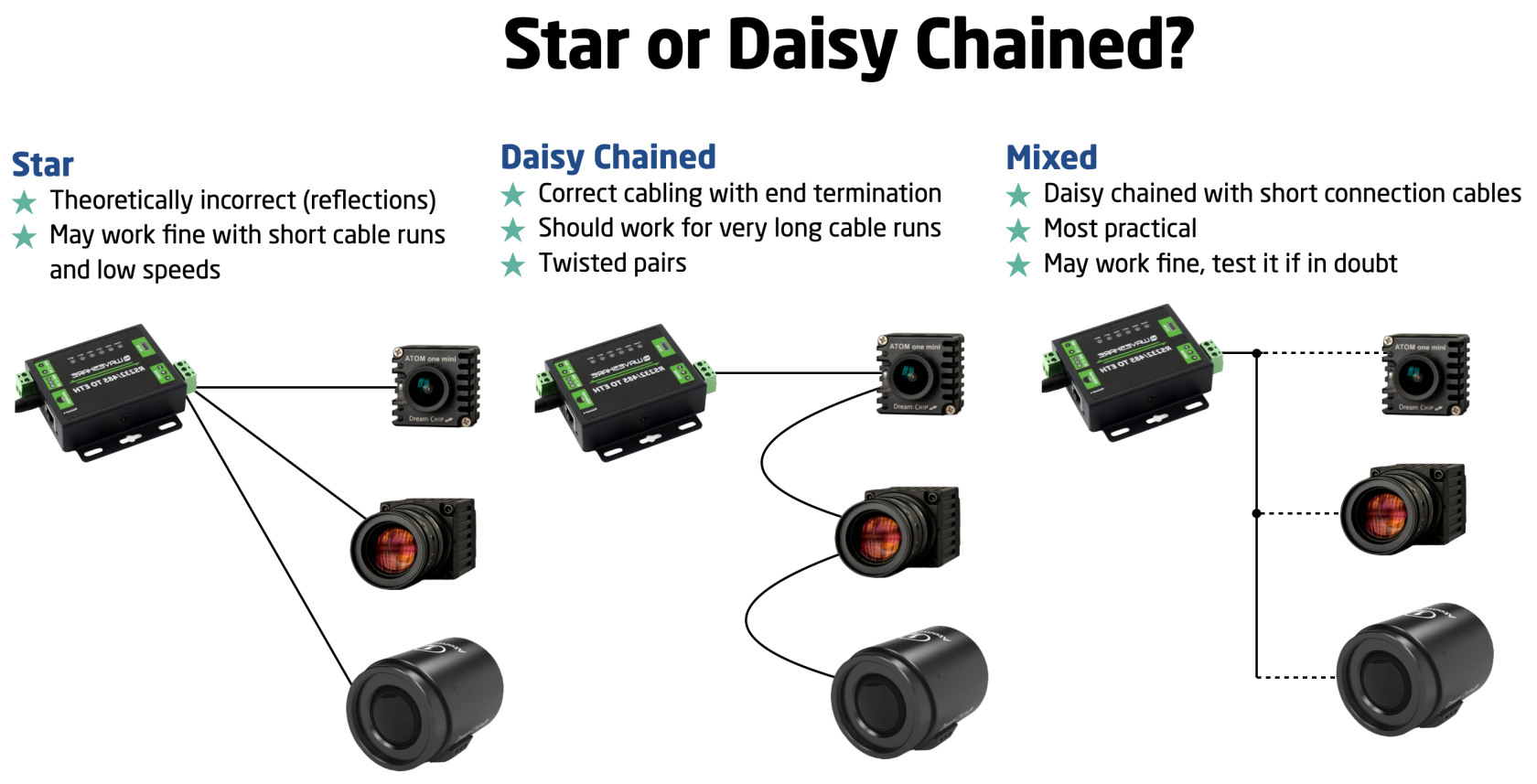](https://wiki.skaarhoj.com/uploads/images/gallery/2023-11/fERimage.png)
Please note that while there is a theoretical standard for this process, there's often some flexibility for slight deviations. However, SKAARHOJ cannot provide specific guidance on these limits; we encourage you to explore and learn from your own experience.
### Setup Video
*\[A video is on the way....\]*
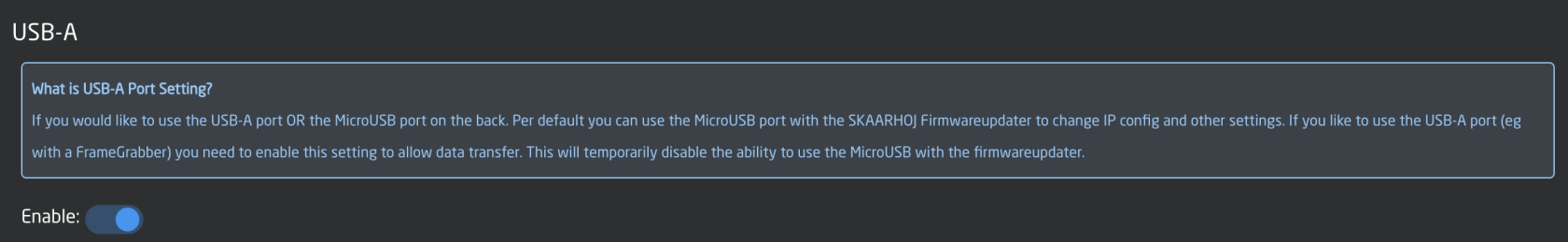
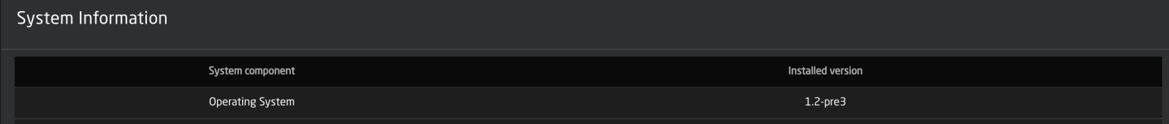
### USB-Serial
The USB-Serial connection requires a SKAARHOJ device with a USB-A port, available on models like the XC8 and Blue Pill Server. Activate the USB-A port via the controller's Settings page. Ensure your device runs skaarOS version 1.2-pre3 or higher.
[](https://wiki.skaarhoj.com/uploads/images/gallery/2023-11/1Z6125126104-dreamchip-001.jpeg)
[](https://wiki.skaarhoj.com/uploads/images/gallery/2023-11/QHFimage.png)
[](https://wiki.skaarhoj.com/uploads/images/gallery/2023-11/7Evimage.png)
For the USB-Serial converter, choose 'USB-Serial' as the connectivity method in the device setup, leaving other fields empty.
[](https://wiki.skaarhoj.com/uploads/images/gallery/2023-11/EAXimage.png)
Using a USB hub for multiple connections is feasible, though the assignment order may be random upon startup.
In the *core-dreamchip-cam* logs, you should see a message like this that confirms connectivity over USB:
[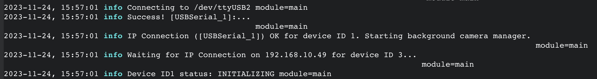](https://wiki.skaarhoj.com/uploads/images/gallery/2023-11/Vyuimage.png)
### Websocket for SSM500
For the SSM500, select 'Websocket' as the connectivity method. This allows the device core to directly connect with the camera. Enter the camera's IP address and leave all other fields blank.
[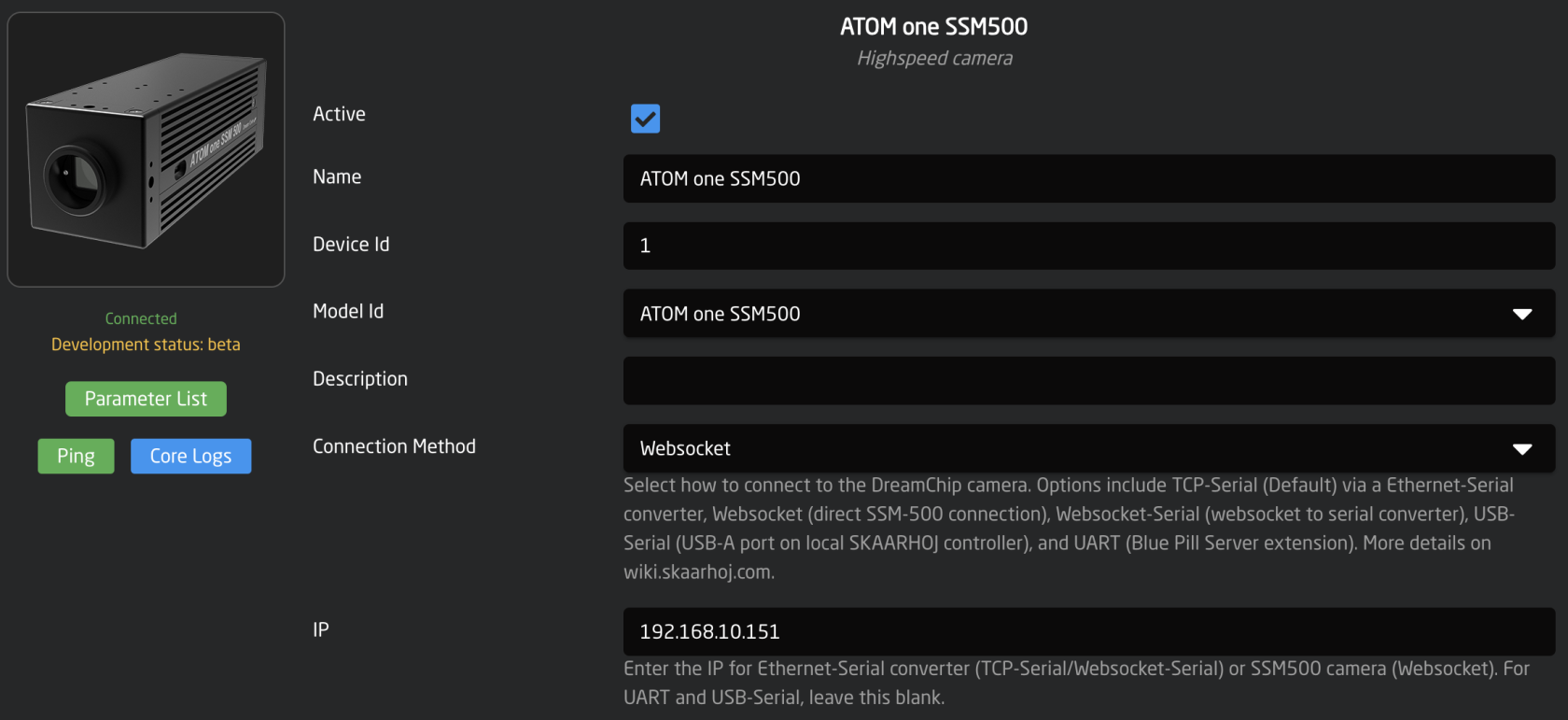](https://wiki.skaarhoj.com/uploads/images/gallery/2023-11/iOsimage.png)
### Websocket-Serial
With some firmware versions of the WaveShare RS232/485 Ethernet converter, 'Websocket-Serial' is available as a connectivity option, with the default port being 6432. However, there's no clear advantage of using Websocket-Serial over the more common TCP-Serial, although it is supported as an alternative.
[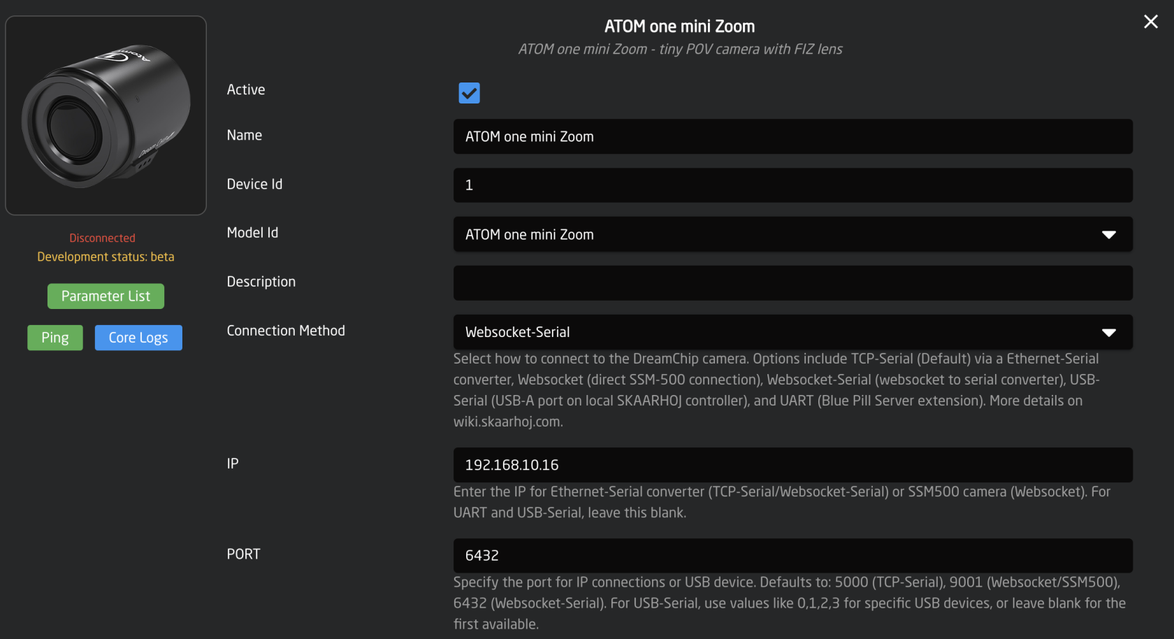](https://wiki.skaarhoj.com/uploads/images/gallery/2023-11/zFuimage.png)
In the WaveShare Serial converter you should find two menu pages that looks like this if it supports websocket connections for RS485:
[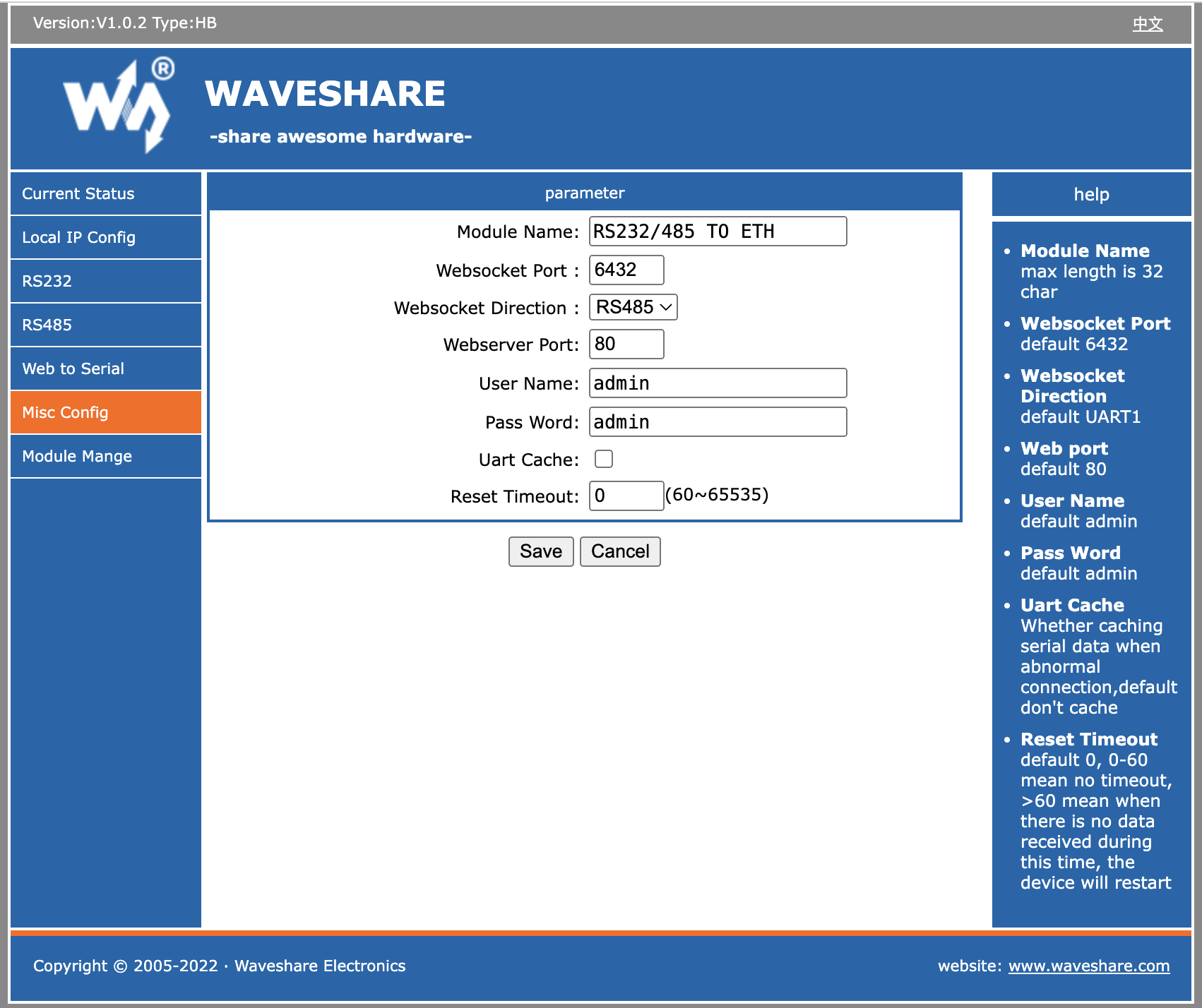](https://wiki.skaarhoj.com/uploads/images/gallery/2023-11/screenshot-2023-11-28-at-15-14-01.png)
[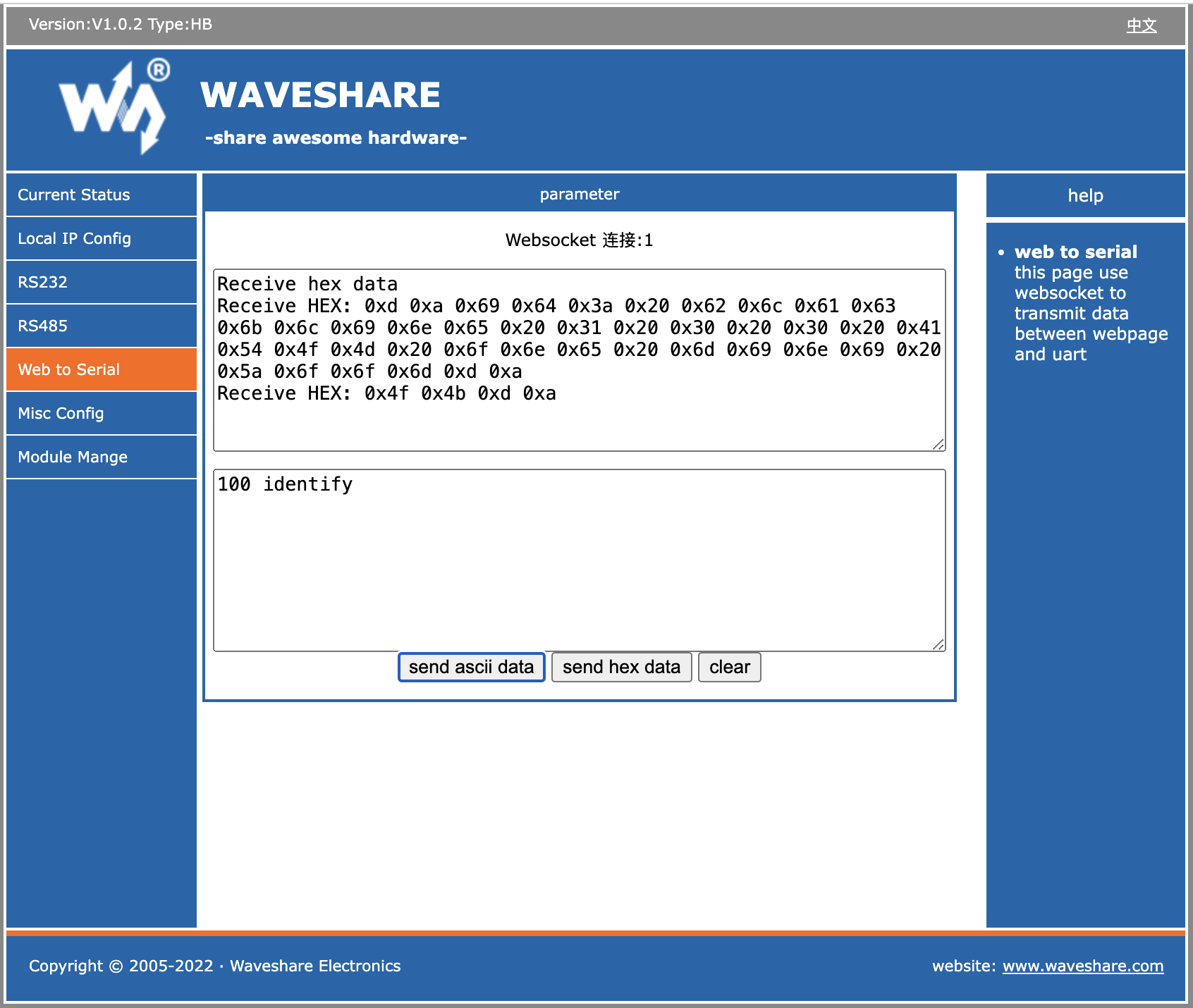](https://wiki.skaarhoj.com/uploads/images/gallery/2023-11/screenshot-2023-11-28-at-15-13-54.png)
### Ethernet-Serial Converters
Set up Ethernet-Serial converters using the 'TCP-Serial' connection method in the device configuration, and include the IP address. Only specify the port if it differs from the default 5000, which should be verified in your serial converter's settings. If using multiple cameras on a single converter, ensure their RS485 addresses are unique. This is adjusted with the 'rs485\_addr' command, followed by saving the settings.
[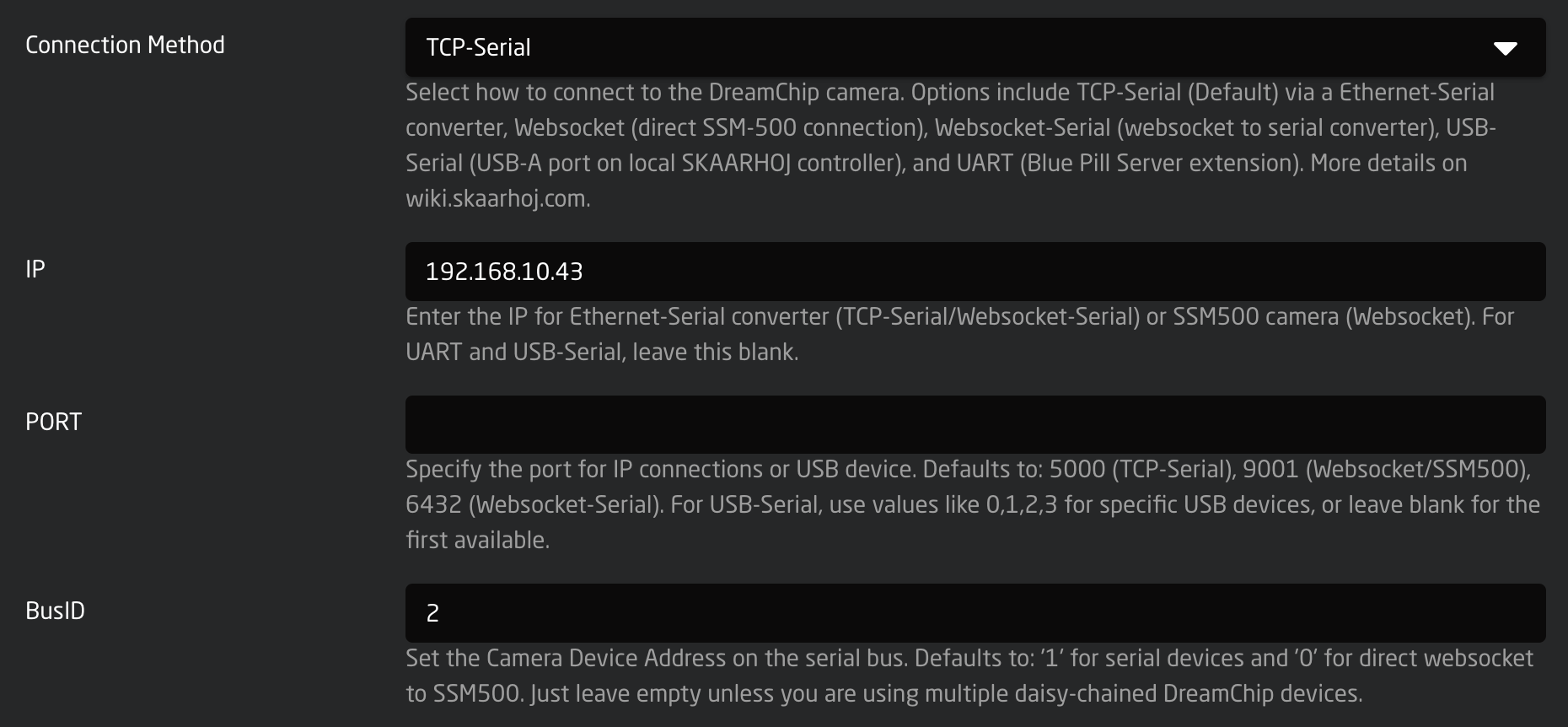](https://wiki.skaarhoj.com/uploads/images/gallery/2023-11/reWimage.png)
In the example, the BusID is set to '2', which is not typical. Usually, you should leave the field empty as most cameras default to an ID of '1'.
##### Changing Bus ID (RS485 Address) of a DreamChip camera using the Ethernet converter
To change a camera's ID on the bus, use a telnet application like Putty, nc, or telnet. Type '100 identify' to see the responding cameras. To change the ID of camera '1' to '2', enter '1 rs485\_addr 2', then confirm with '100 identify'. Save this ID change for future boot-ups by typing '2 save\_settings' (2 is the new ID!); the camera will reboot. If you encounter issues, consider using DreamChip's ProVideoGUI application for Windows or consult the camera protocol manual.
### Ethernet-Serial Converter Cabling
Using the standard DreamChip cable is preferred if possible. It's a very simple setup:
[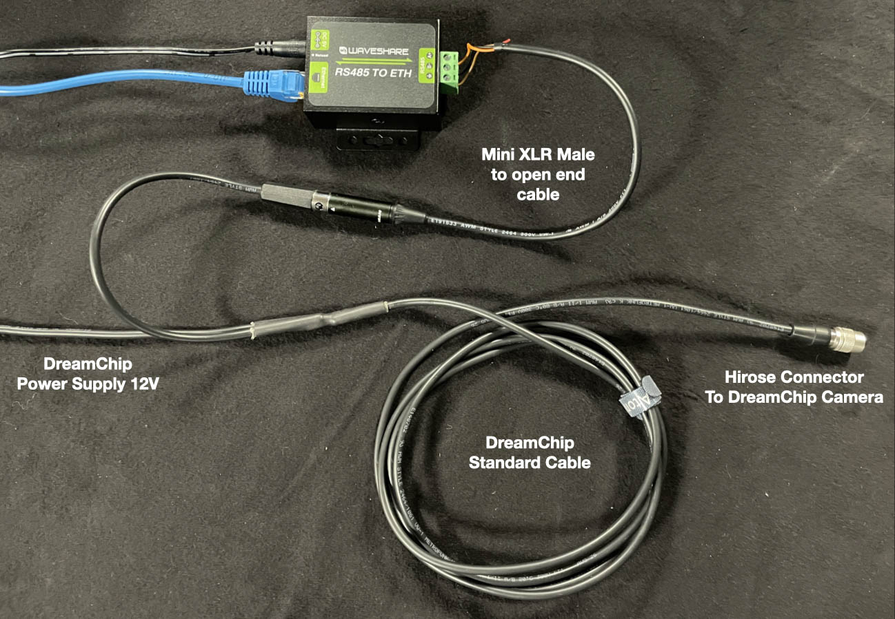](https://wiki.skaarhoj.com/uploads/images/gallery/2023-11/G5h125126104-dreamchip-002.jpeg)
To connect your DreamChip camera to an Ethernet Serial converter of any type, you need a Mini XLR male cable with open wires in the other end. Then you connect it in the following way:
- T+(A) => mini XLR pin 1
- T-(B) => mini XLR pin 2
- GND = mini XLR pin 3
[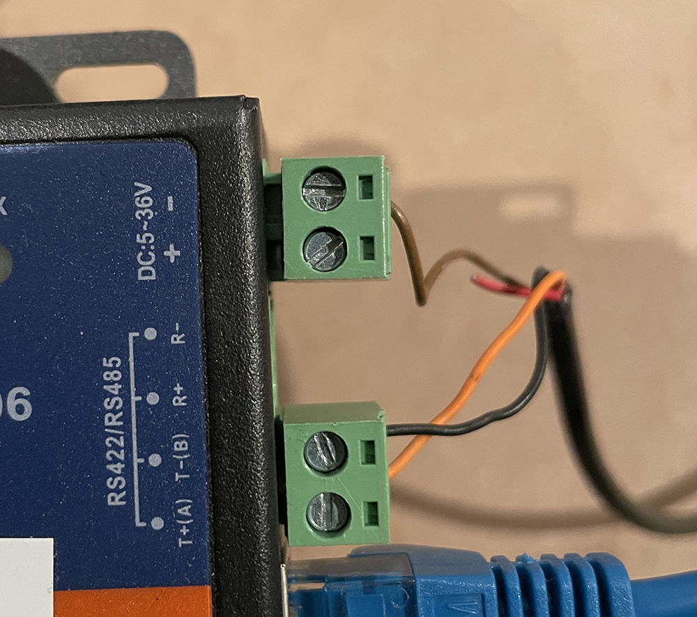](https://wiki.skaarhoj.com/uploads/images/gallery/2022-03/image-1647512462854.png)
To achieve a multi camera star connection, you simply insert multiple cables in the converter (for short cable runs). You can also use the power passthrough to have one supply to the converter (12V) feed the camera. Be sure to feed 12V into the converter:
[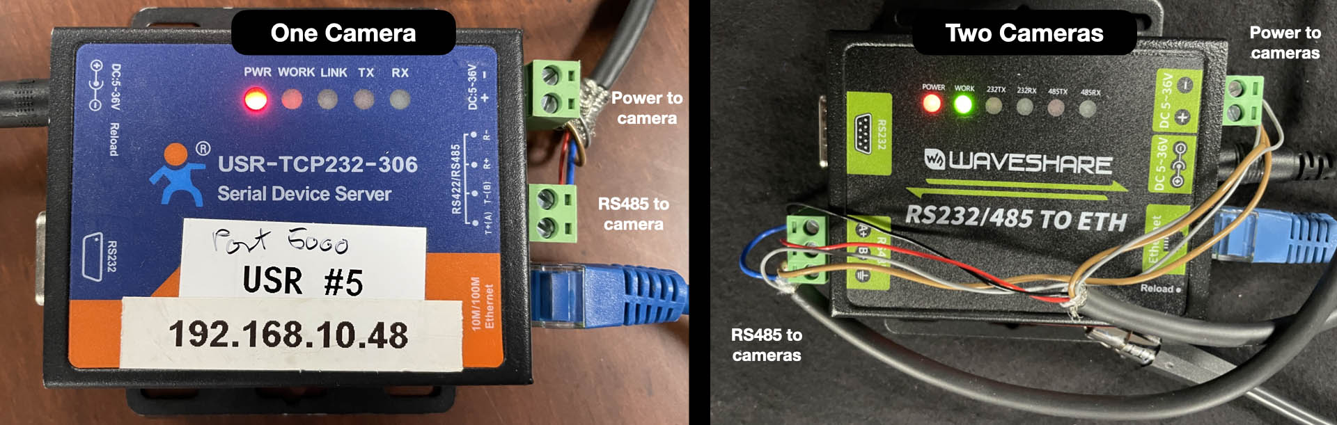](https://wiki.skaarhoj.com/uploads/images/gallery/2023-11/125126104-dreamchip-003.jpeg)
### Test connection
To connect to the converter using a terminal, employ 'nc' (netcat) or telnet on port 5000. 'nc' sends LF as the line ending, but the SSM500 camera responds to both 'LR' and 'CRLF'. Upon connection, you won’t see a greeting message, but typing '100 identify' and pressing enter will prompt a response from the camera. For example:
**kasper@Kaspers-MBP-2 ~ % nc 192.168.10.48 5000**
100 identifyid: caterham\_hs **1** 0 0 ATOM one SSM500OK
In this instance, we’re connecting to a converter at IP 192.168.10.48. The command sent to the camera is followed by the camera's response. The response indicates the camera's ID (in this case, '1'). With multiple cameras on the same serial bus, each will respond with its ID. Here’s an example with ATOM One, ATOM One Mini, and ATOM One Mini Zoom:
100 identifyid: xbow 1 0 0 ATOM oneOKid: cooper 2 0 0 ATOM one miniOKid: blackline 3 0 0 ATOM one mini ZoomOK
Note: The converter allows multiple IP connections, but camera responses are broadcast to all clients, irrespective of the command sender. DreamChip cameras are not designed for multiple masters. Only one IP client should actively communicate with the camera, while others may listen. For multi-master setups with DreamChip, use a SKAARHOJ Blue Pill Server with the DreamChip device core for a compatible multi-master interface.
### Recommended Ethernet-Serial Converters
Follow the provided instructions to connect your Ethernet-Serial converter to your network. For WaveShare converters, the default IP is 192.168.0.7. Once connected, configure the Serial setup as shown below for compatibility with DreamChip cameras.
These converters appear to originate from the same factory or brand. While they are not identical and have varying features and behaviors, they most likely represent different iterations of the same platform.
#### WaveShare RS232/485 To ETH
[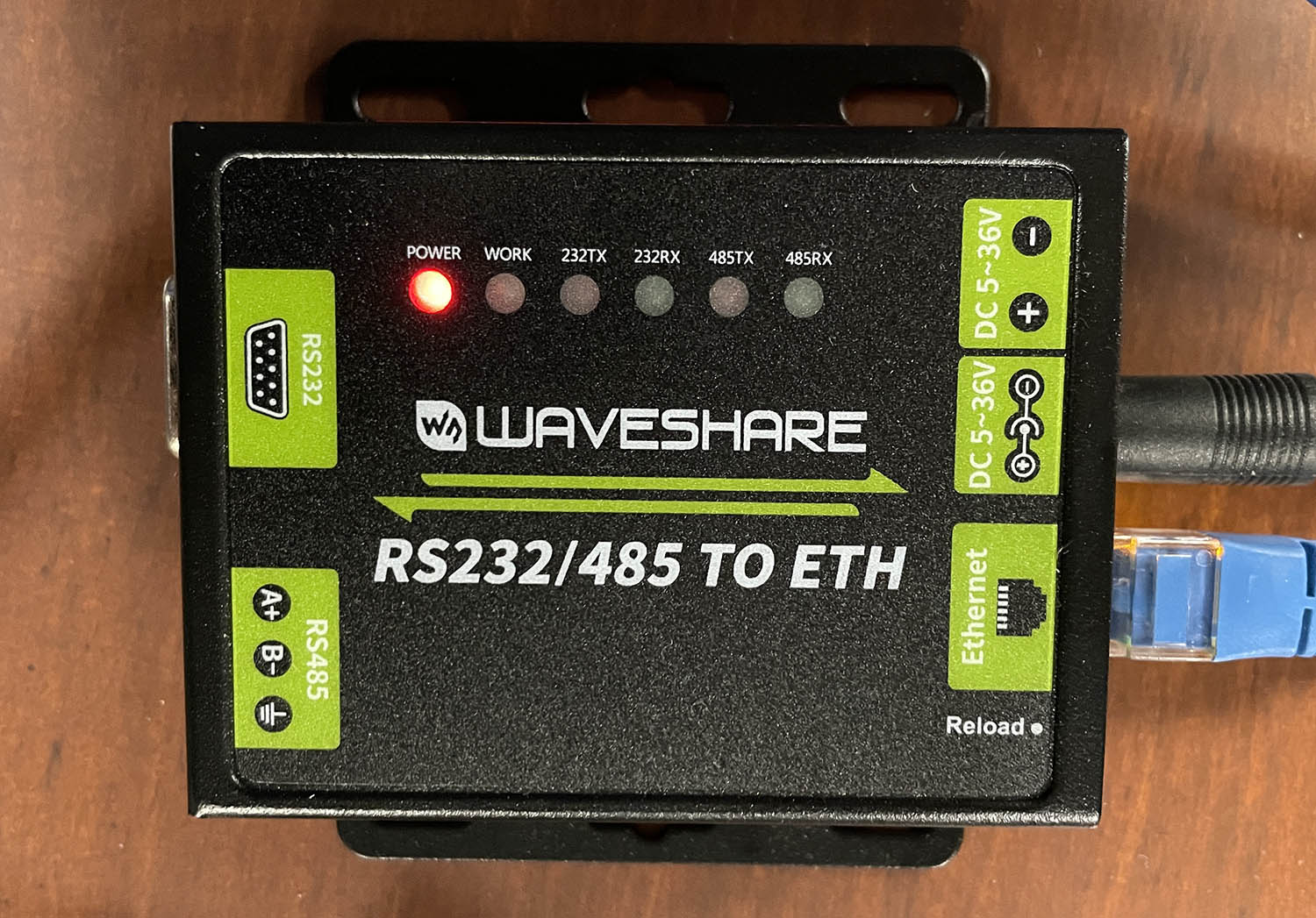](https://wiki.skaarhoj.com/uploads/images/gallery/2023-11/img-8831.JPG)
[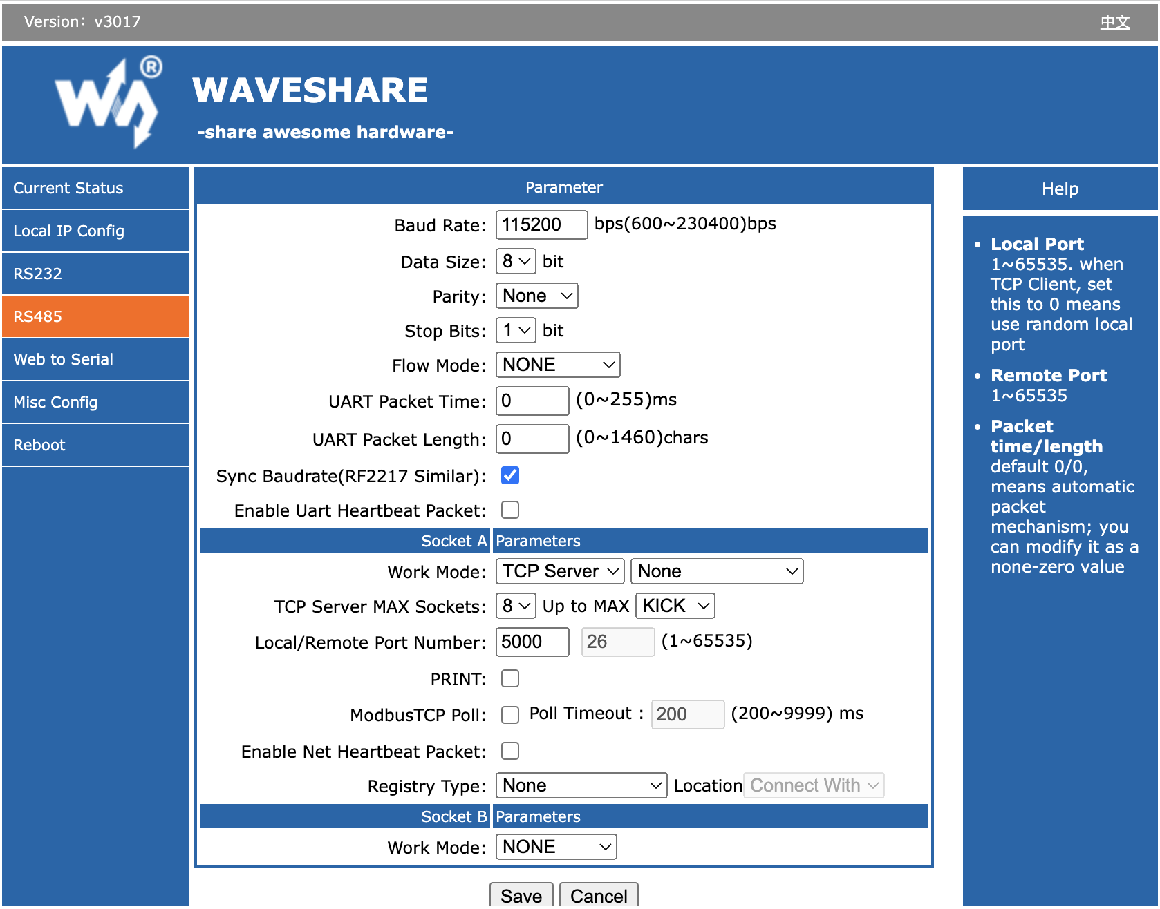](https://wiki.skaarhoj.com/uploads/images/gallery/2023-09/ncBimage.png)
#### WaveShare RS485 To ETH
[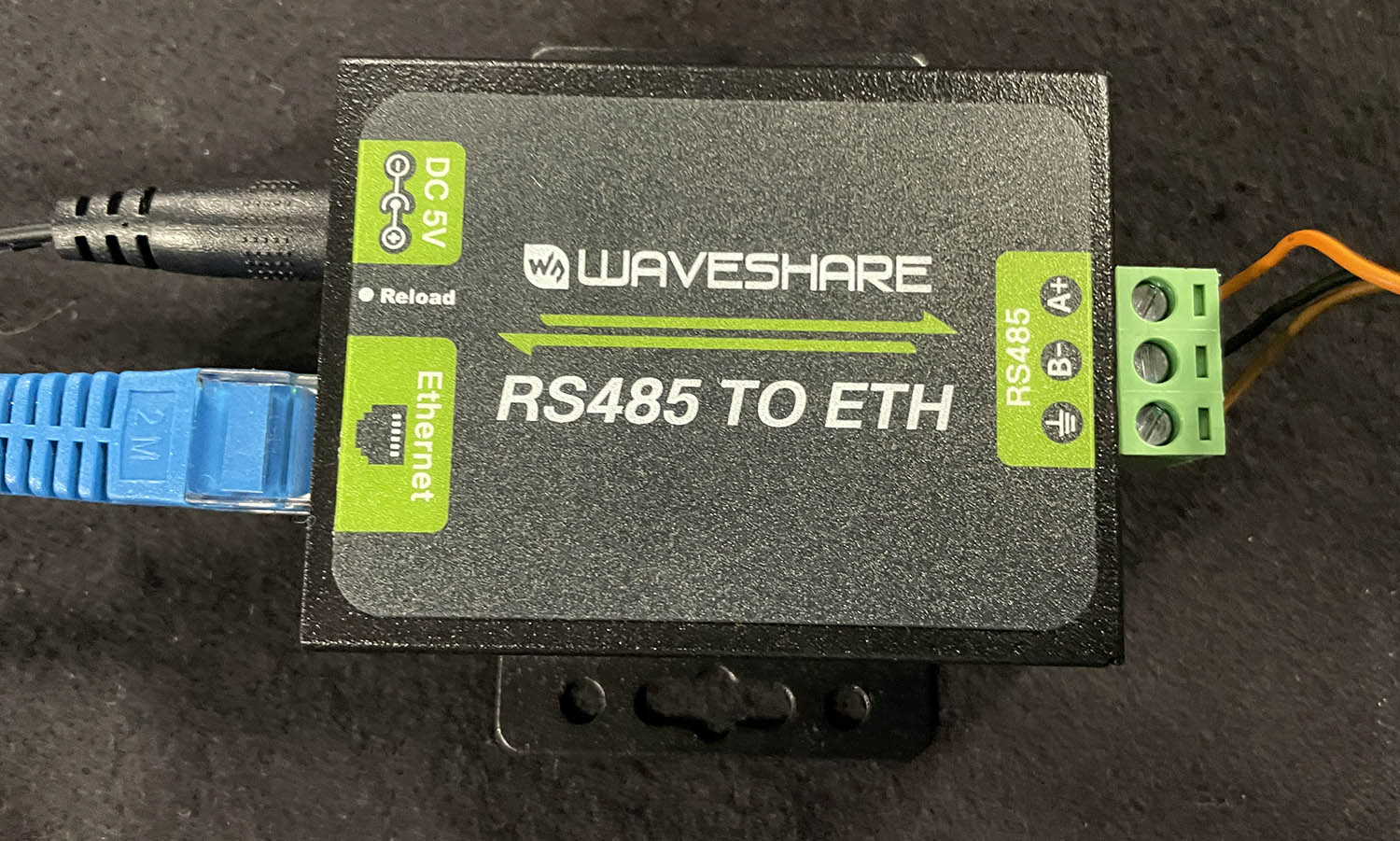](https://wiki.skaarhoj.com/uploads/images/gallery/2023-11/img-8830.JPG)
[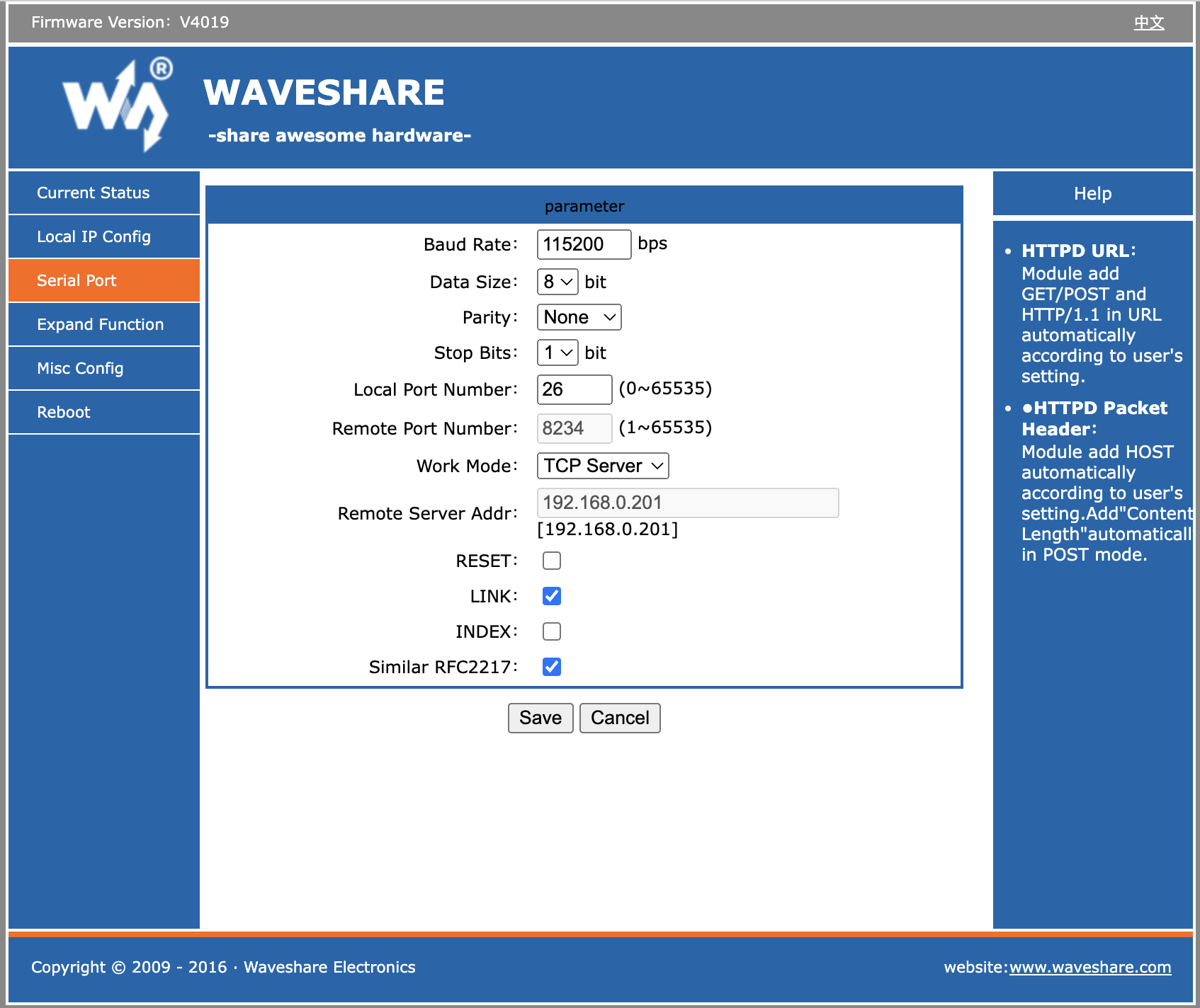](https://wiki.skaarhoj.com/uploads/images/gallery/2023-11/btKimage.png)
Note: Here we left the port (Local Port Number) at "26". We would normally change this to 5000 to make it compatible with our default values in the device core.
#### USR-TCP232-306
[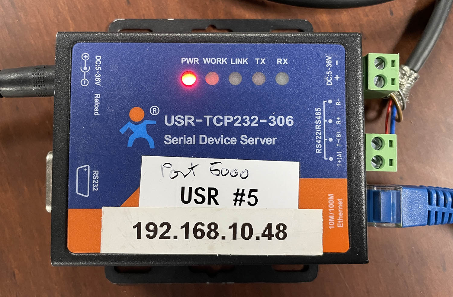](https://wiki.skaarhoj.com/uploads/images/gallery/2023-11/img-8832.JPG)
[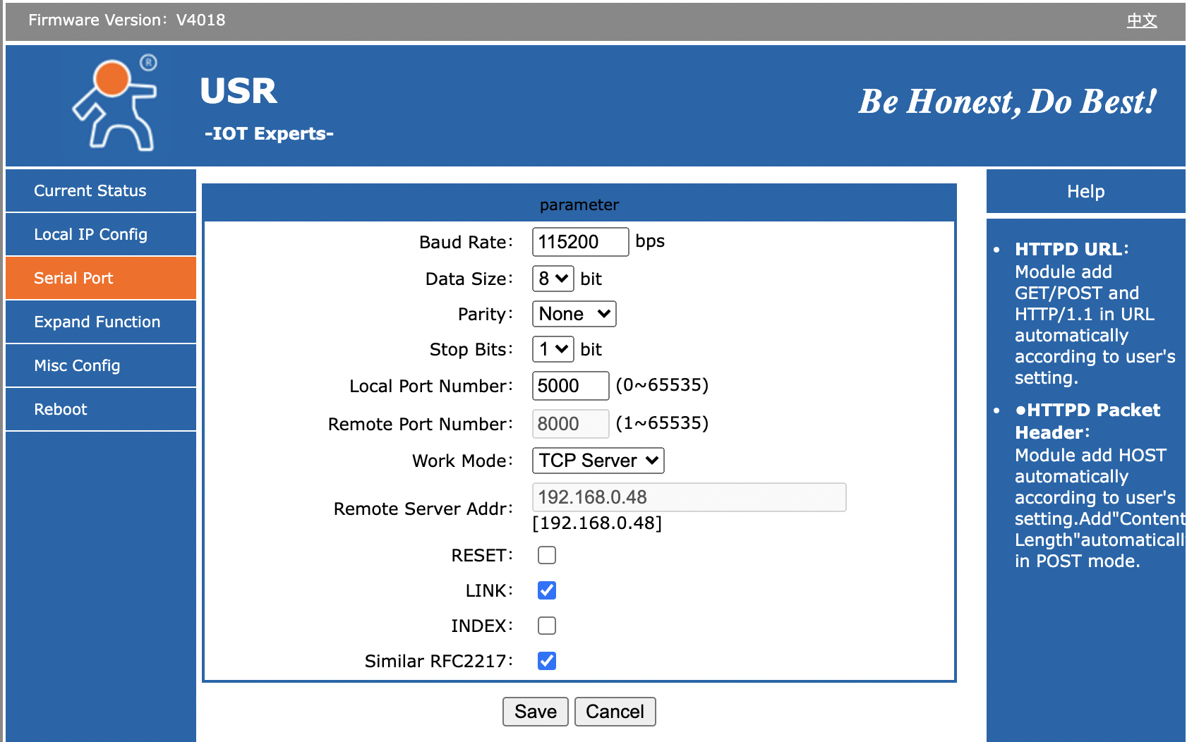](https://wiki.skaarhoj.com/uploads/images/gallery/2022-03/image-1647512470167.png)
- Baud Rate: 115200
- Data Size: 8 bit
- Parity: None
- Stop Bits: 1
- Local Port Number 5000
- Work Mode: TCP Server
**Bug on USR-TCP232-306:** It looks like the red TX and green RX LEDs on top of the unit is labeled wrong: On one or more of the units we have tested, it's clear that RX will blink green as we send out content on the serial bus and TX blinks red as we receive content. It feels more intuitive that the TX LED should blink in that case (and vice versa).
The "Link" LED will light up when the device has a network connection. It may not turn of if you pull the plug though - apparently it won't detect such a disconnect.
### Other Ethernet-Serial Converter Options
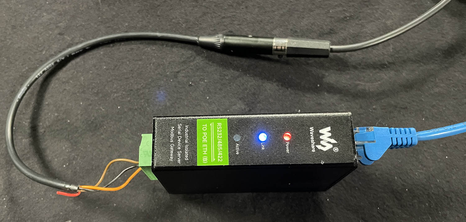
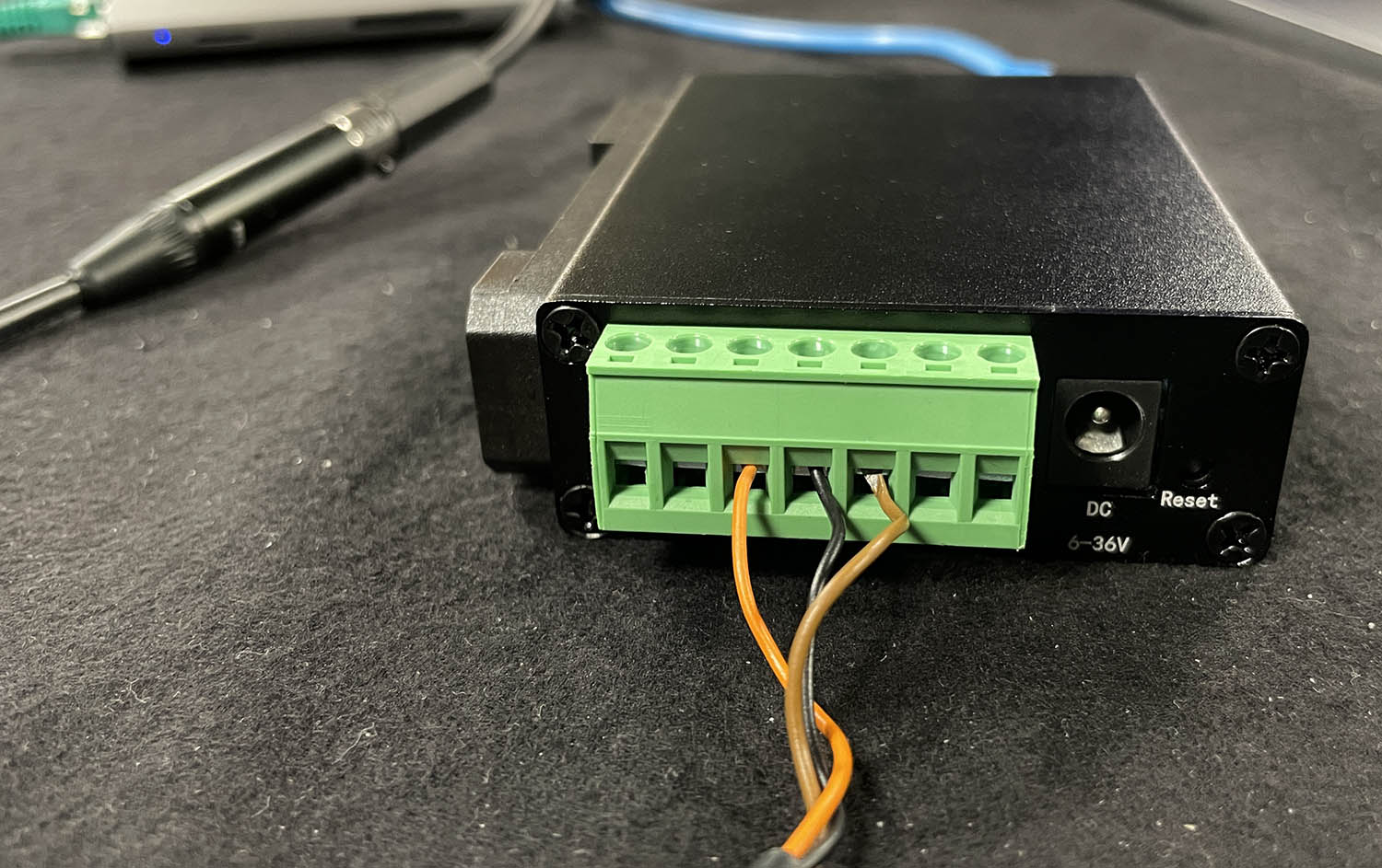
#### WaveShare RS232/485/422 TO POE ETH (B)
[https://www.waveshare.com/rs232-485-422-to-poe-eth-b.htm](https://www.waveshare.com/rs232-485-422-to-poe-eth-b.htm)
[https://www.waveshare.com/wiki/RS232/485/422\_TO\_POE\_ETH\_(B)](https://www.waveshare.com/wiki/RS232/485/422_TO_POE_ETH_(B))
PoE powered converter for DIN rail mounting. Default serial port: 4196 with 115200 baud and tested with ATOM One Mini Zoom. Perfect reconnection on loss of connection. Factory Reset to IP 192.168.1.254.
*Note: By default: No web UI on port 80, may need to use Windows tool to configure that!*
[](https://wiki.skaarhoj.com/uploads/images/gallery/2023-11/img-8861.JPG)
[](https://wiki.skaarhoj.com/uploads/images/gallery/2023-11/img-8862.JPG)
[](https://wiki.skaarhoj.com/uploads/images/gallery/2023-11/img-8863.JPG)
#### PUSR USR-W610
[https://www.pusr.com/download/WIFI/USR-W610-User-Manual-V1.0.1.01.pdf](https://www.pusr.com/download/WIFI/USR-W610-User-Manual-V1.0.1.01.pdf)
The device functioned well when connected via cable, but we encountered difficulties in setting up the Wi-Fi. Despite numerous attempts to connect it as a client to my Access Point, we were unable to get the Wi-Fi to work. This issue is particularly significant since the primary purpose of this device is its Wi-Fi capability. Due to this, we cannot recommend it.
[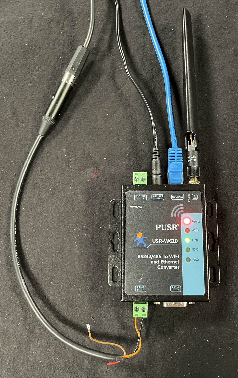](https://wiki.skaarhoj.com/uploads/images/gallery/2023-11/img-8864.JPG)
# Ember+ DeviceCore
The Ember+ DeviceCore allows bluepills to control Ember+ Systems as Consumers. Using the built in Ember+ Explorer you can browse your devices Ember Tree and configure which parameters are going to be used. Check out this QuickStart Video for setting up your device
# Eth-B4 Link Lens Control
Skaarhoj Eth-B4 Link offer a way to control iris on B4 lens separate from the camera they are connected to. You can find initial device set up in the device manual: [Skaarhoj B4 Links Manual](https://github.com/SKAARHOJ/Support/blob/master/Manuals/Tutorials/Skaarhoj_B4_Links.pdf)
Firmware versions can be found here: [Standalone Firmware Downloads](https://www.skaarhoj.com/support/standalone-firmwares "Standalone Firmware Downloads")
Connecting the device inside Blue Pill is simple.
1. Add the Eth-B4 Link as a device on the home page.
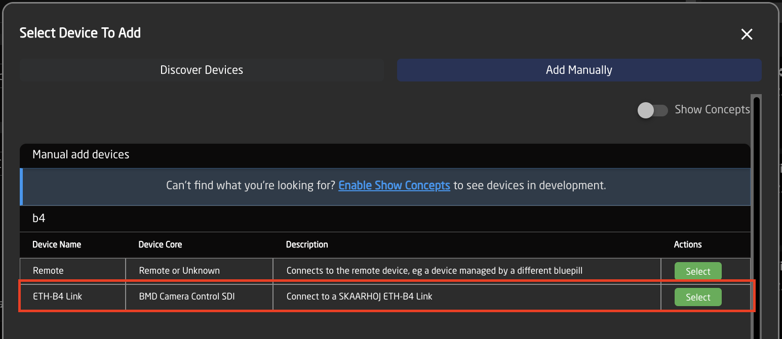
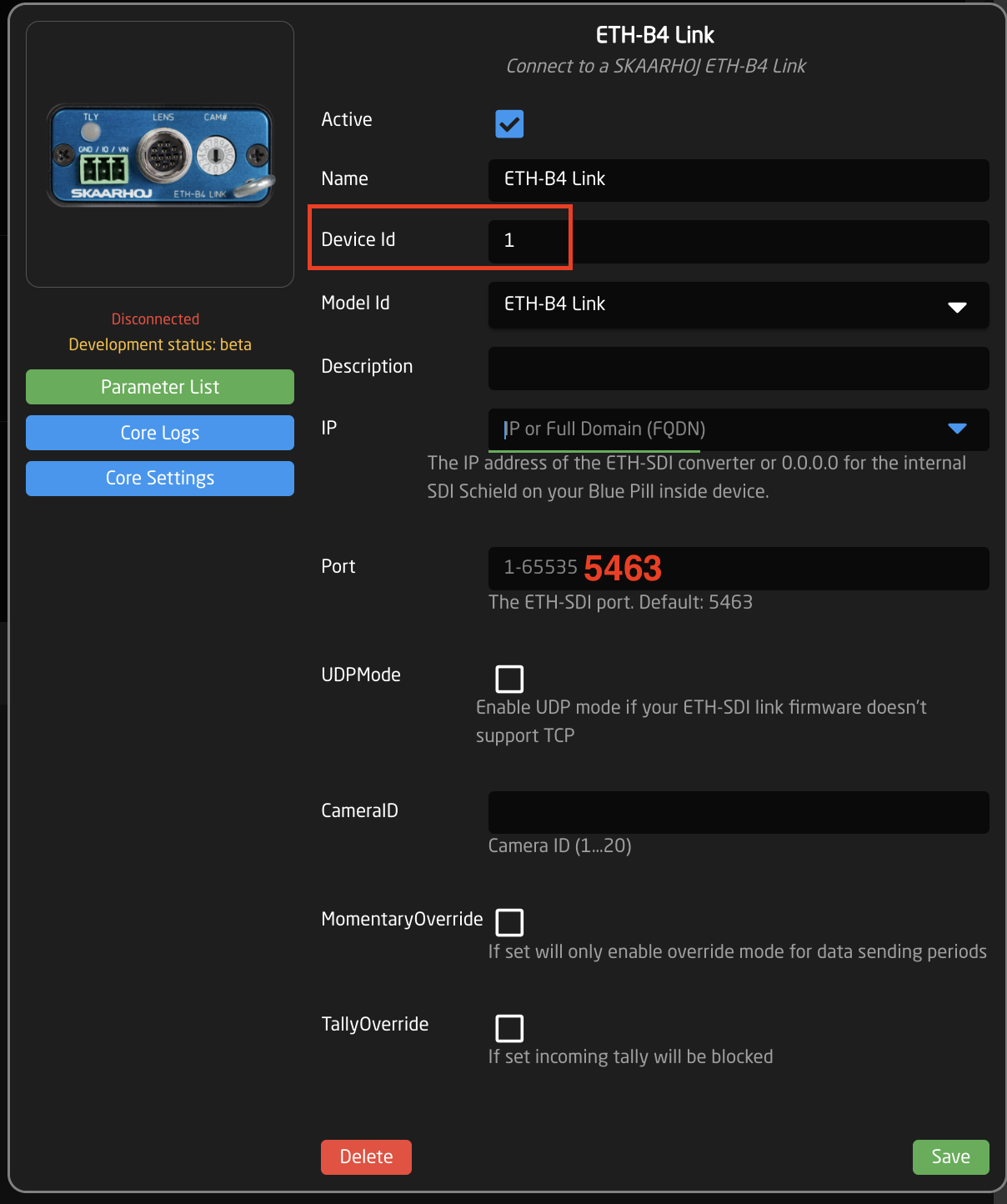
2. In the device details:
Add the IP address of the Eth-B4 Link as the IP of the camera.
The Port is 5463.
Set the Camera ID to match the camera number.
The Name is however is easiest for you to identify it.
The Device ID needs to match the Device ID number of the camera you are connecting it to. If you have your setup includes multiple types of cameras using different device cores (example: a Red and an Arri camera), make sure the Device ID for each camera is unique to help tie it to the B4 Link and lens.
Save
3. In the Camera Selector constant set for the Skaarhoj Panel, under Iris Channel Config, select: BMD Cam Control Iris.
Please Note: the Device ID number is used here to tie the camera and the B4 Link/lens together. If two cameras had the same Device ID, they would have conflicting lens control.
This setup does not use the core-analog-b4 device core package or the B4 Analog via Blue Pill Extension Iris Channel Config.
#### Calibration And Setup Of The ETH-B4 Link
Now that we have that out of the way. Let's look at how we can use this new controller. This will work when controlled by either the Unisketch or Blue Pill platform.
##### Calibration For Use With Unisketch
If you are using the ETH-B4 Link with a Unisketch controller, please download the manual and follow the Calibration steps in there, for how to ensure that your ETH-B4 Link is calibrated.
In short, connect the lens to the unit, move the selection wheel to the "F" or "15" position and wait for it to show a solid Green on the Tally LED. then your unit is fully calibrated. Power cycle the device and it's ready for use.
##### Calibration For Use with Blue Pill
When paired with Blue Pill, please clear the config on the unit, in essence, it's ready to go out of the box. To clear the calibration move the wheel to the "E" or "14" position and wait for the solid "Green" light. Power cycle the device and it's ready for use.
The iris limiting is done by reactor instead, directly from the controller. This is done by holding down "Shift" on the panel and using the "Max" and "Min" buttons that should now appear on the panel. move the joystick/fader on your panel to the furthest position up where the lens reacts and click "Max" then move the lens to the lowest position where the lens reacts or depending on how dark you wanna be able to go, and click "Min". Then your joystick should now limit you to only being able to control within that range, to clear the calibration just hold down the top edge on the button you want to reset.
"Iris Max" = More light, so lower F-values, or joystick/fader up
"Iris Min" = Less Light, so higher F-values, or joystick/fader down
Here can be seen where to find these min/max calibration buttons on some different controllers, while holding shift:
### Setup And Tuning Of the PID controller
*Relevant for units on firmware v1.0.3 and forward*
On firmware v1.0.3 and forward we have added a PID controller to help with the precision, particularly on older lenses. the default tune that the firmware comes with is based on internal testing for the best all-around performance, but might not give an accurate F-stop reading/position on all lenses, but should be better than on older firmware.
If you want to disable this and get back to how it was on v1.0.2 you can do that via the serial monitor in the SKAARHOJ updater. Just type "pid-en=0" and you will be back to how it was.
First of we have a set of new serial commands to work with on the unit for controlling and manipulating the PID controller, and those are:
- "pid=?" - Get the current PID settings as well as if it's enabled.
- "pid=<num>,<num>,<num>" - Sets a new set of settings by setting Kp, Ki, and Kd respectively, more info on this later
- "pid-en=1" - Turn on the PID controller (this is the default)
- "pid-en=0" - Disables the PID controller and it's now working as it was on firmware v1.0.2, might be useful for some users.
- "pid=reset" - resets the PID settings to how they came by default in the firmware
PID controllers can be tricky to calibrate and tune but allow a lot of control and customisation. We have done some in-house testing over a handful of B4 lenses, of different ages, including one box-lense. And found what we would call a good starting point, it's not the most precise but it's also not the worst. But it should perform pretty identically on a 20-year-old lens vs a 1-year-old lens. It's recommended to have a play at this if you like to tinker or if you think it's missing something for your specific lens. Maybe it's a little slow for your liking or maybe it stutters a bit on your lens. In any case, playing with it and the PID values is not something to be afraid of, as you would not be able to damage your lenses with it as they are limited internally. And if you get way out, you can always run the PID reset command or manually paste in the default or a known working set of values.
For info on how to tune a PID controller, we would recommend reading up on what a PID controller is and what the values fully mean, there are some great resources out there that will do a better job at it than what we could do. Below are some links to some of these places:
- [Wikipedia: Proportional–integral–derivative controller](https://en.wikipedia.org/wiki/Proportional%E2%80%93integral%E2%80%93derivative_controller)
- [DigiKey: What is a PID Controller?](https://www.youtube.com/watch?v=tFVAaUcOm4I&ab_channel=DigiKey)
- [SiieeFPV: PIDs Simplified](https://www.youtube.com/watch?v=6OH-wOsVVjg&t=5s&ab_channel=SiieeFPV)
The default PID values that our unit comes with are:
- Kp: 20.0, Ki: 0.16 and Kd: 0.0 running at 50hz
- pid=20.00, 0.16, 0.00
Some of our notes from internal testing of other values that might make good starting points for different uses are:
- pid=20,0,0 - Stutter but accurate, works nicely on old lenses (a bit slow)
- pid=20,0,20-20,0.01,50 - Less stutter, but still there, loses accuracy in the high f values
- pid=75.00,0.1,50.00 Kinda works, D can go to 500
- pid=20.00,0.25,30.00 - Pretty smooth, but overshoot
- pid=20.00,0.20,30.00 - More smooth, with less overshoot, less accurate
- pid=20.00,0.18,0.00 - Low-end fits, little overshoot, pretty smooth
- pid=20.00,0.16,0.00 - Smooth, minor overshoot on quick big jumps, not super F-value correct (The current default setup)
# HTTP Device Core
The HTTP Device Core for Blue Pill, *core-protocol-http*, allows users to send and to some extend receive and process information via HTTP requests. Effectively, this can help to bridge communication with devices with RESTful APIs where a dedicated device core is not available.
The device core has a basic mode and some more complex features that can come in handy in some cases. It has been designed to align with the feature set of the corresponding HTTP Client device core on the UniSketch platform, but it's far more robust and easy to extend to include new approaches.
### Basic Configuration
Each device in the device core has the usual configuration available. Looks like this:
[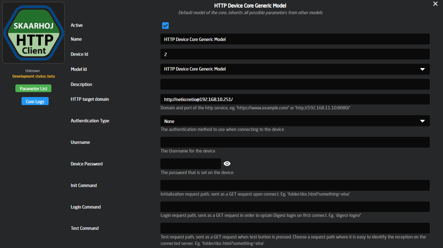](https://wiki.skaarhoj.com/uploads/images/gallery/2024-02/image.png)
- The HTTP Target Domain is set up here. All individual commands will consist of paths under this domain. Notice that the username and password are also entered here in clear text.
- The Init Command is a path under the HTTP Target Domain to be requested in a GET request as the core initializes.
- The Login Command is the path under the HTTP Target Domain to be requested as a GET request to get the DIGEST login nonce, used to log in to the device on the first request sent. (if none the HTTP Target is used as is)
- The Test Command is a path under the HTTP Target Domain to be requested in a GET request when the Test trigger is activated (that's typically available as a button in Reactor).
- Authentication Type defines the type of authentication (login) that your device uses, if you have a username and password defined as part of the HTTP Target Domain then that will overwrite this and be used instead, this field is also only relevant if the username and password are specified below it.
- Username is only used if the Authentication Type is set, and will also get ignored if the username and password are specified in the path
- Password is only used if the Authentication Type is set, and will also get ignored if the username and password are specified in the path
### Cowboy Style
The most straight forward way to use the device core would be to send one-shot triggers *cowboystyle*. This requires only a minimum of configuration but provides the least amount of long term convenience. This is probably a good place to get started.
[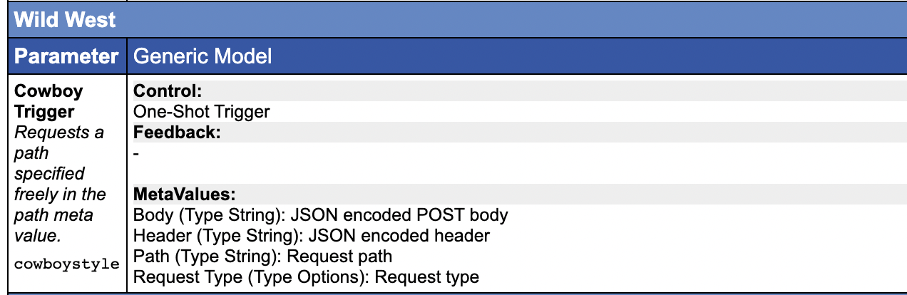](https://wiki.skaarhoj.com/uploads/images/gallery/2022-10/iOximage.png)
Notice the meta values here - they are essentially the configuration for the individual requests.
Adding a Cowboy Trigger to a panel is basically a matter of combining this parameter with a SKAARHOJ:Trigger master behavior:
[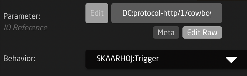](https://wiki.skaarhoj.com/uploads/images/gallery/2022-10/biKimage.png)
The Meta value fields are the key to the whole thing. They would look like this:
[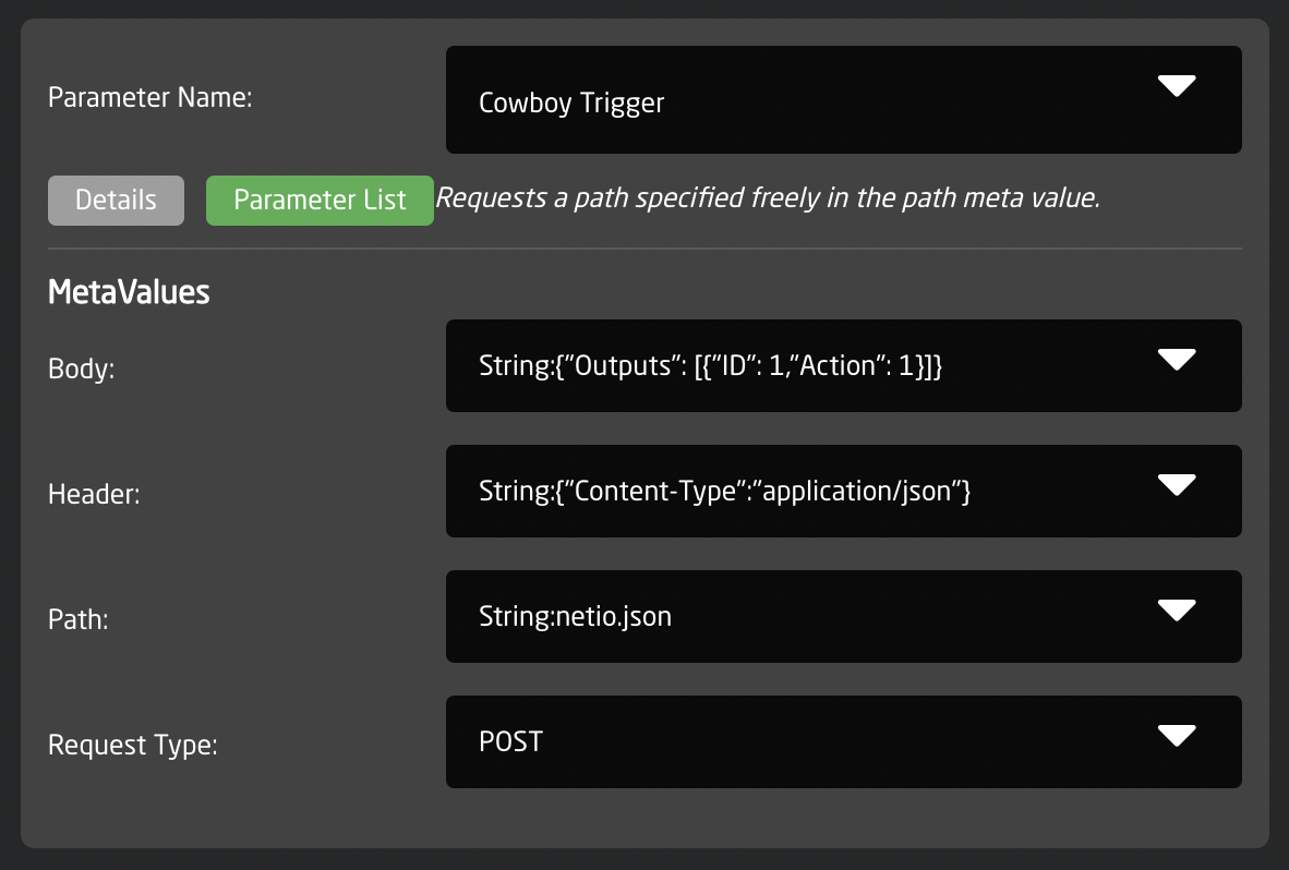](https://wiki.skaarhoj.com/uploads/images/gallery/2022-10/d12image.png)
- The **Path** meta value is the path under the HTTP Target. Here it is "netio.json", could be "directory/file.ext?id=value&...." etc.
- The **Request Type** is the type of HTTP request. Standard is GET, but POST, PUT, PATCH, DELETE are other options you can use here.
- The **Header** shall be a JSON object where each key in the object corresponds to an HTTP header that will be set for the request
- The **Body** shall be any content that is used as the body in the requests as they support it. This is used for POST requests.
The meta fields are in fact so called **IO references** in Reactor and that means you can insert references to device cores, variables, constants etc. For example, some of these values could be derived from a constant like "Behavior:Const:Body". This is important because the value gets parsed and pasting pure JSON into these fields won't work, so to make sure a complex string like **JSON** gets correctly picked up, it **must be prefixed "String:"** as you see in the examples.
Now, go have fun, shoot from the hip and see how far you get that way... :-)
### Command Configuration
The device core allows you to configure a number of fixed commands too. The advantage is that you can bundle an A and B command into a single action for toggles etc. Also, this is the way you can use meta values with the \\p1,\\p2, ... placeholders etc. like you can for the TCP and UDP device cores. Finally, it's actually possible to decode some level of status back from the returned content of the device via a regular expression.
Below you see the example from the cowboy style trigger, but with some level of parameterization applied now:
[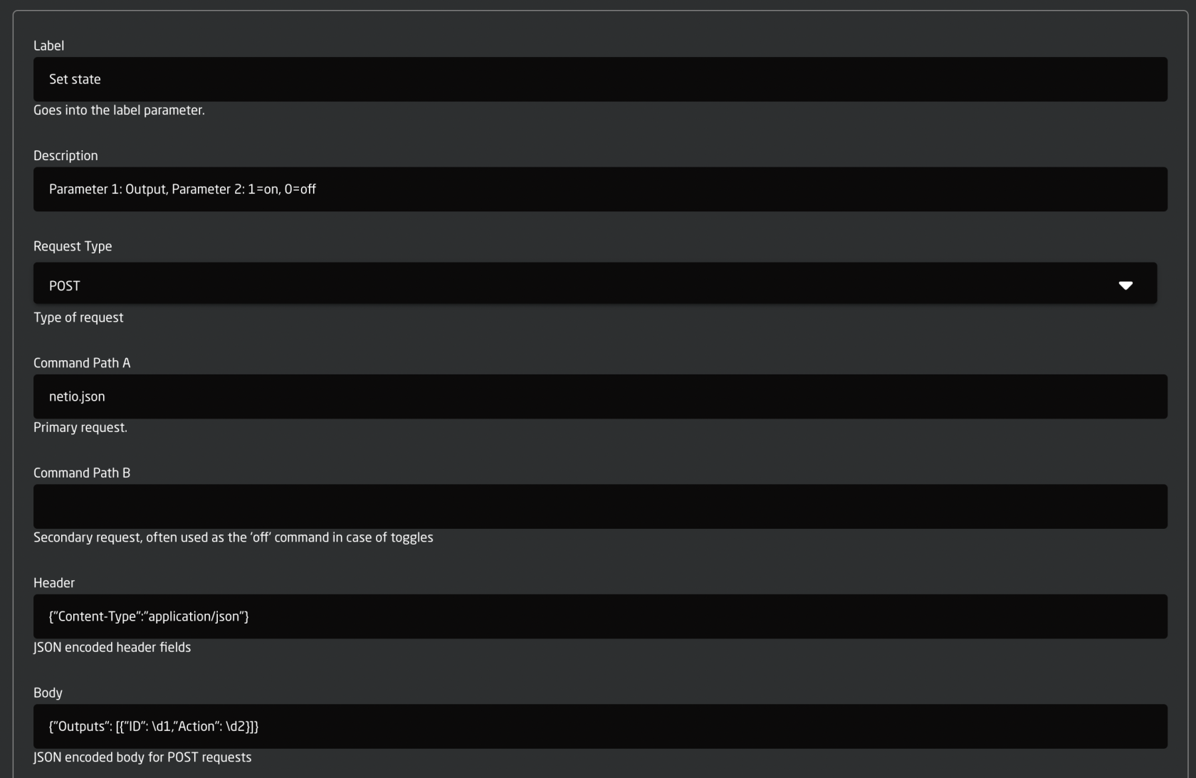](https://wiki.skaarhoj.com/uploads/images/gallery/2022-10/sbOimage.png)
- The **Label** field will be set as a fixed value in the device core so you can import it as a label in Reactor. This could be used as a title in Reactor.
- The **Command Path A and B** are available to easily create toggle functionality. In this case, Command Path A is set to "netio.json"
- **Header** is straight forward JSON content type.
- The **Body** field has new features: The \\d1 and \\d2 are two placeholders that allow us to import values from the meta fields of the device core parameters we will use for the fixed commands, namely Toggle, On Trigger and Off Trigger
In reactor this can be applied to a button in this way:
[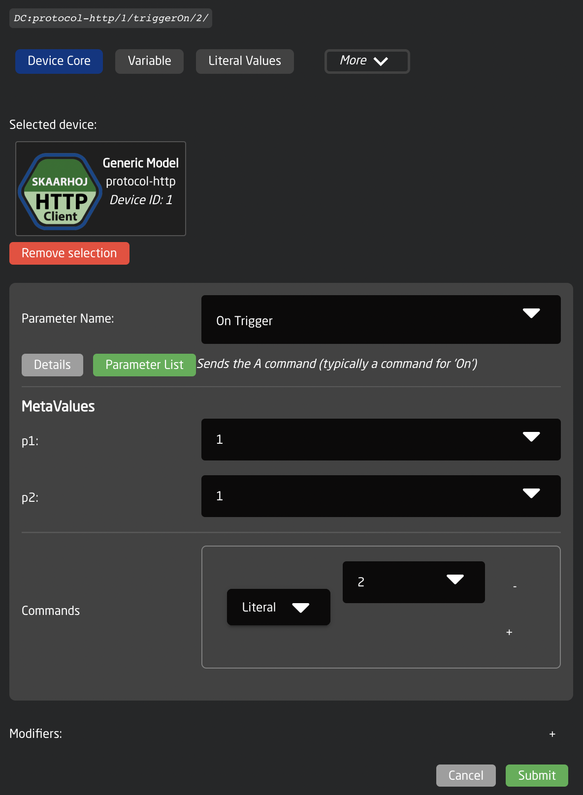](https://wiki.skaarhoj.com/uploads/images/gallery/2022-10/dj7image.png)
- The values for p1 and p2 are 1 and 1. p1 is the ID of the feature we want to turn on and p2 = 1 is the same as "on" according to the protocol.
- Commands has the value 2 and that is the number of the command from the configuration.
So to make a similar trigger for off, we can use the same command (2) but change the value of "p2" to 0 instead.
### Parsing response and periodic requests
It's possible to parse the response of any request and let a matching part of that response get stored in the device core. This is done by the Matching Return Value field that contains a regular expression. You can study the format of regular expressions elsewhere, but they are basically very powerful and advanced string matching patterns.
Whenever the device core receives feedback from the server it will run the regular expressions set up for the command and if there is a match, it will take the value in parenthesis and store as the status value in the corresponding Status parameter. It's both possible for triggered requests as well as for periodic requests.
Here is an example:
[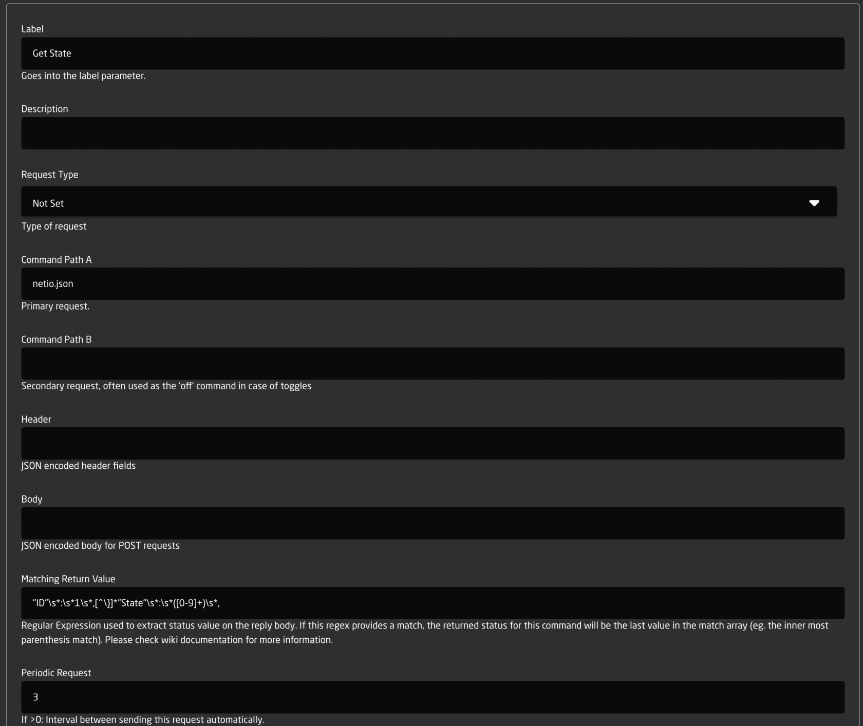](https://wiki.skaarhoj.com/uploads/images/gallery/2022-10/h4uimage.png)
- Generally, it's really simple. The path is "netio.json", the request type is not even set (so it defaults to GET) and there is no header or body.
- The Matching Return Value is "ID"\\s\*:\\s\*1\\s\*,\[^\\}\]\*"State"\\s\*:\\s\*(\[0-9\]+)\\s\*, - yes, that's true. Explained a bit more below...
- The Periodic Request is 3 - so every three seconds we will call this URL, parse it and store the contents in the Status parameters for this command.
Now, the return body from this request would look this way:
> {
> "Agent":{"Model":"3PF","DeviceName":"PowerBOX-E7","MAC":"24:A4:2C:38:DF:E7","SerialNumber":"24A42C38DFE7","JSONVer":"2.2","Time":"1970-01-01T16:51:29+01:00","Uptime":13889,"Version":"2.4.3","OemID":300,"VendorID":0,"NumOutputs":3},
> "Outputs":\[
> {**"ID":1,"Name":"PTZ (T8)","State":1,**"Action":6,"Delay":2020},
> {"ID":2,"Name":"Power output 2","State":0,"Action":6,"Delay":2020},
> {"ID":3,"Name":"PoE Switch","State":0,"Action":6,"Delay":2020}
> \]}
And the regular expression will match exactly the portion of this JSON response that is highlighted in red. All the "\\s\*" is precautions to make sure any whitespace doesn't throw our parsing off, and there is an assumption that the ID attribute comes before the State attribute, but otherwise it should be a good example of how a regular expression can be built to provide some robustness towards variations. In the above case we have to bypass the Name attribute for example.
The main point is that the value of the State attribute is what we are after, but only when found for ID 1. To capture that value, we enclose it in parenthesis: "....(\[0-9\]+)...."
And this happens every three seconds, so we are essentially monitoring the device for state change - on a single feature! And this also underlines the reason why SKAARHOJ generally integrates device cores custom to each device: There is just not efficient way to get *all the state* from any device by manually building up a ton of such expressions, capturing only one aspect at a time. And feedback from devices is the holy grails of quality integrations that are not simple pray-and-forget approaches to control.
But... now you have got it for the occasional case where there is only this type of "workaround" to get the job done.
### Placeholders
The Body and the Path of requests are subjected to placeholders (see also the TCP and UDP device cores):
- **\\n** and **\\r** will send a newline or carriage return (bytes 10 and 13)
- **\\xHH** will send a byte with the value HH (in hex): so **\\xFF** will send a byte with value “255”, for more than one byte, apend the number of bytes up to 8 after the backslash, like this: **\\4xFFFFFFFF** this will send: \[255 255 255 255\] and **\\2xFFFF** will send \[255 255\] (remember 2 characters to one byte).
- **\\p1** or **\\p2** (alternatively **\\d1, \\d2, \\h1, \\h2**) will insert a parameter value as defined by the meta value p1 and p2 in the device core parameters Toggle, On Trigger and Off Trigger.
The difference between using \\p, \\d and \\h is whether the meta value is inserted as the byte value (\\p), inserted as a decimal number like “255” or “37” or “3” (\\d - there are no leading zeros) or in hexadecimal like FF or D0 or 00 (\\h - in this case, it’s always two characters and uppercase). Using \\p is limited to one byte, so 0-255 values, both \\d and \\h will scale to support any int value up to 32 bits.
- **\\d1**, **\\d2**, **\\h1** and **\\h2** support appending 0's to conform to always sending a set number of digits or bytes. to do this add the number of digits in front of d and h, this also effectively limits your max value to the set amount of digits. The command structure is like this: **\\<0-9>d<1-2>** so if we want to send the decimal value 255 with 4 digits from param1 we use **\\4d1** and it will send 0255 and the same for hex, using **\\4h1** we will get 00FF sent in the message. using **\\0d1** or **\\0h1** is the same as not using a number and will just scale to the minimum needed to show your value with no leading 0's
- **\\s1, \\s2 In core v1.0.5-pre1 and newer:** this will parse the value as a raw string, if you need to escape it for use in the Path A or Path B URLs, please do that before filling in the value, other than that it should be supported in all of the data fields.
# Kessler Crane
### Adding and connecting to a Kessler Crane device from the Blue Pill platform
The Blue pill can connect to a Kessler Crane device in two ways, via WiFi or USB. In both cases, there are some special things that needs to be handled for the Blue Pill Core to connect successfully.
First, add your desired device inside the reactor, by clicking the add device and selecting "Add Device Manually". Then search and click add on your desired model.
[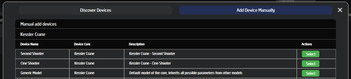](https://wiki.skaarhoj.com/uploads/images/gallery/2022-07/image-1657270287772.png)
You should now be prevented with this device config box:
[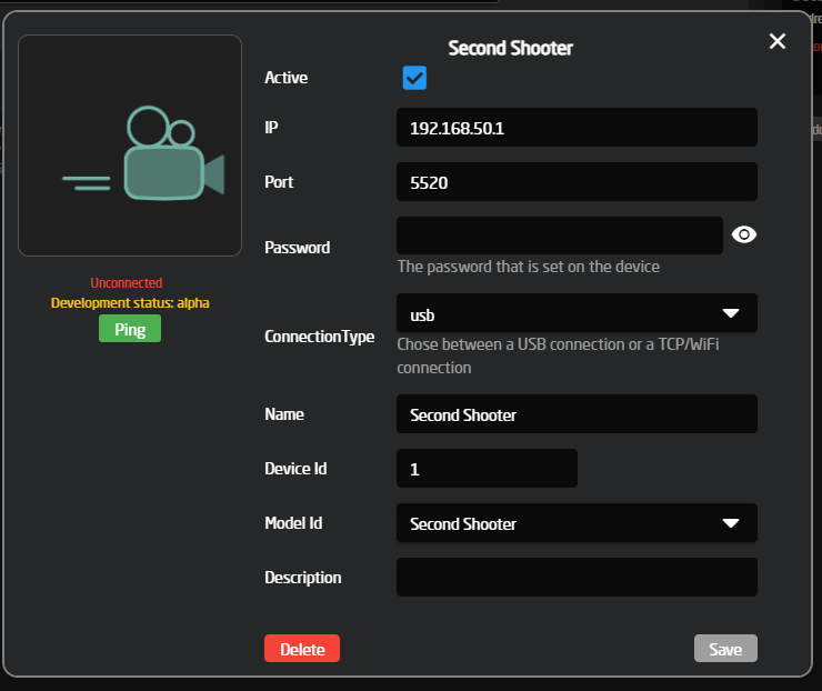](https://wiki.skaarhoj.com/uploads/images/gallery/2022-07/image-1657270736037.png)
If your config box does not have the "Connection Type" option, please click the save button and wait until you see the device on the left side say "Disconnected" or "Connected". If it's your first time installing the core, it will say "Installing Core" wait for that to finish, then restart reactor to load the new Device Config structure.
Clicking this "running" button will give you the option to restart reactor:
[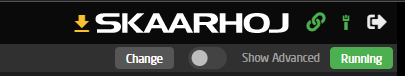](https://wiki.skaarhoj.com/uploads/images/gallery/2022-07/image-1657271066379.png)
After restarting reactor, click on the device on the left side, and you should now see the "Connection Type" inside the device config popup. Please set this option to your desired setup type and continue the setup below.
Updating your SkaarOS and enabling USB-AFor the Kessler core to connect over USB, you must be on **SkaarOS v0.14-pre2** or newer and have the USB-A connector enabled on the settings tab.
#### Update SkaarOSTo update SkaarOs, go to "Settings" and click "Update".
[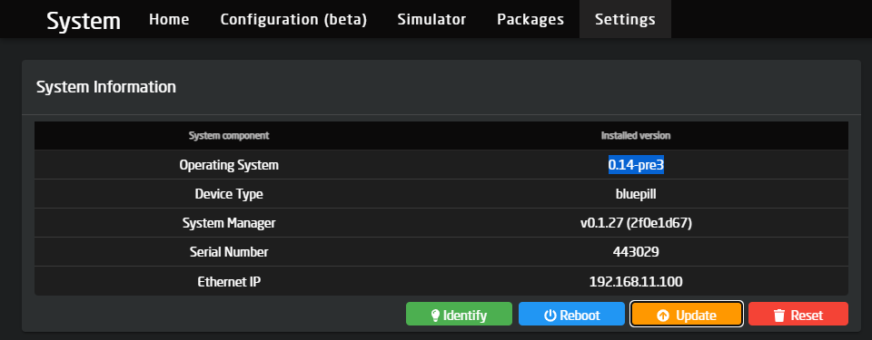](https://wiki.skaarhoj.com/uploads/images/gallery/2022-07/image-1657272707368.png)
This will give you a popup where you select the v0.14 stable version (or higher). If you don't see a stable version for v0.14, enable "Show Pre-Releases" and choose the newest version available, the minimum supported version we need is v0.14-pre2. Then click update and **wait **for the Blue Pill to finish installing and restart the device.
[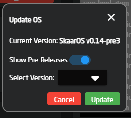](https://wiki.skaarhoj.com/uploads/images/gallery/2022-07/image-1657272819340.png)
*Note if you do not see the prerelease option, scroll down to settings and enable "Advanced Mode"*
#### Enable the USB-A connector
To enable the USB-A connector on a Blue Pill device, please go to "Settings" and scroll down to enable it here:
[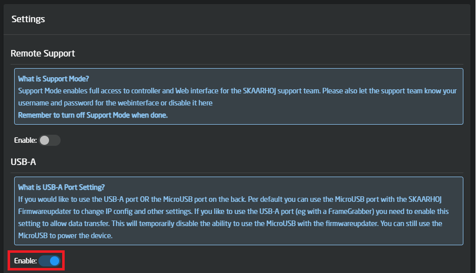](https://wiki.skaarhoj.com/uploads/images/gallery/2022-07/image-1657273253186.png)
Connecting over USB
Connecting over USB is very simple but has two caveats that need to be addressed before it will connect.
First, please check with the guide inside the "Updating your SkaarOS and enabling USB" block and make sure you have that set up first.
If you are on a supported SkaarOS version and have the USB-A enabled.
Connect a USB-A to USB-Micro cable between the USB-A connector on the bluepill and the USB-Micro on the Kessler Device.
After that setup the device as shown below, a few things a not in use by the core when connecting over USB and can be left as is, this Includes the IP and Port.
[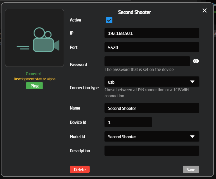](https://wiki.skaarhoj.com/uploads/images/gallery/2022-07/image-1657271798820.png)
If you get a green "Connected" status, you are now ready to use the device. If you do not get that, please open the package logs and check if there are any errors. If you get an error like this one, it means that your SkaarOS might not be on a supported version or that the USB is not enabled/connected on both ends.
[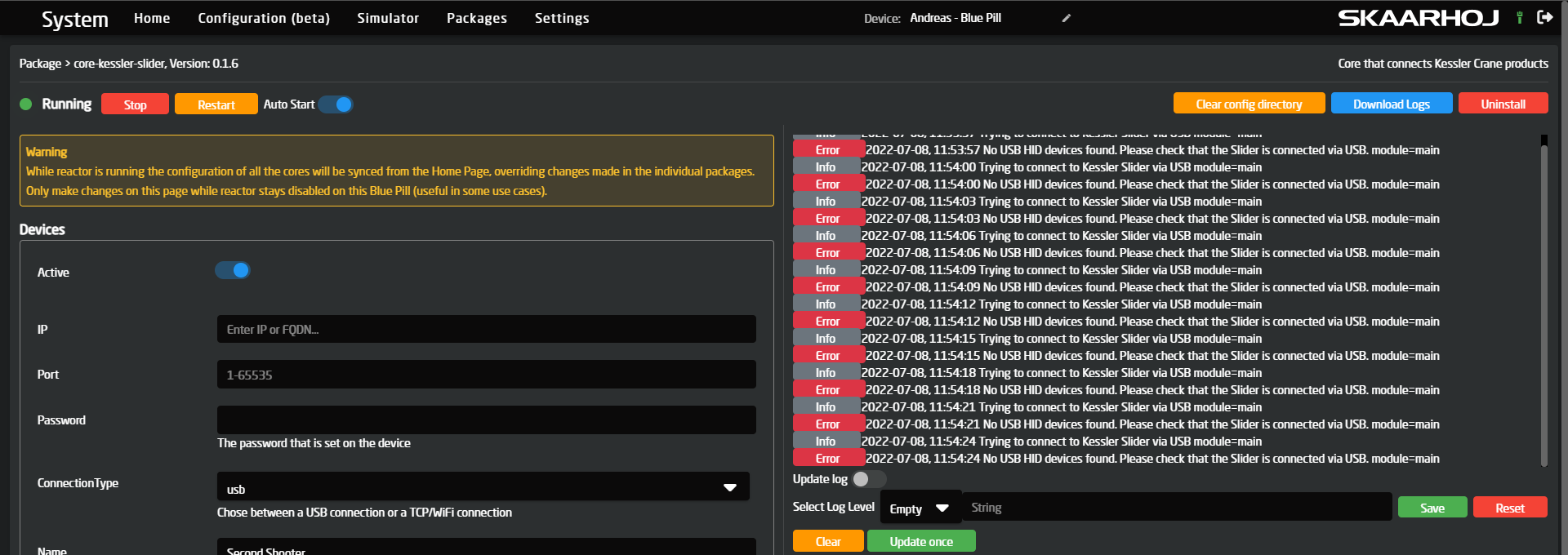](https://wiki.skaarhoj.com/uploads/images/gallery/2022-07/image-1657274081682.png)
Connecting over WiFi
When connecting to a Kessler Crane device over WiFi, you should configure the device like this inside reactor. All the default values should already be correct, as the IP and port of all Kessler sliders are the same when they host their own WiFI.
One thing does need changing from the default, and that is the Connection Type, which needs to be changed from "USB" to "TCP", as it, by default, is set to "USB".
The "Password" field is optional and depends on whether you set a password on the device itself.
The final setup should look like this:
[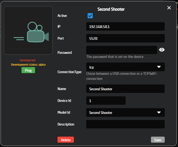](https://wiki.skaarhoj.com/uploads/images/gallery/2022-07/image-1657271830207.png)
More info to be added here about how to enable WiFi on the slider themselves and how to connect to the WiFi...
# MRMC Flair 7 Control with SKAARHOJ
[Flair](https://www.mrmoco.com/motion-control/flair/) is an industry-leading software solution from Mark Roberts Motion Control used to control camera robotics. Quite simply, there is an infinite number of possibilities you can do with Flair when it comes to creative robotic camera movements. From simple arcs, orbits and linear motions, to much more advanced features and control, resulting in pixel-perfect repeatable motions.
SKAARHOJ controllers can tie into the workflow with Flair to improve the user experience. For example, you can
### Setup
Flair runs on a PC, and when the application runs, there is usually a terminal window in the background. You need to know the IP address of the PC and type that into the configuration of the SKAARHOJ Flair Device Cores configuration. When connected, you will see this on the side of Flair:
[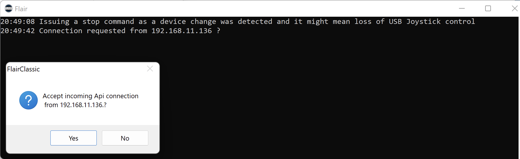](https://wiki.skaarhoj.com/uploads/images/gallery/2022-11/ba2image.png)
In the window you can see that a connection from 192.168.11.136 (SKAARHOJ controller) was requested and you answer "Yes" in the prompt.
# NETIO PDU settings
[](https://wiki.skaarhoj.com/uploads/images/gallery/2025-01/netio-banner.png)
NETIO PDU's (Power Distribution Units) are network-based power sockets. You can read more about the products on their website: [https://www.netio-products.com](https://www.netio-products.com)
NETIO products have a built-in web UI for initial settings, such as:
- IP address
- API protocol
- Username and password
#### Access web UI
To access the web UI, you simply open a webbrowser and enter the PDU's IP address.
If you don't know the IP address, you can use the NETIO Discover app (for Windows) to discover it on the network. You can download Discover app for free here: [https://www.netio-products.com/en/software/netio-discover](https://www.netio-products.com/en/software/netio-discover)
#### Settings
To have correct control from SKAARHOJ panels (this means both 'read' and 'write') you must use these specific settings:
1. In the webbased UI goto the '**M2M API Protocols**' page.
2. Select '**JSON API**' tab
3. Enable JSON API - must be ON
4. Enable Read-Write - must be ON
5. Enter desired Username and password (typically the same as you use to login to web UI)
6. Click 'Save Changes'
[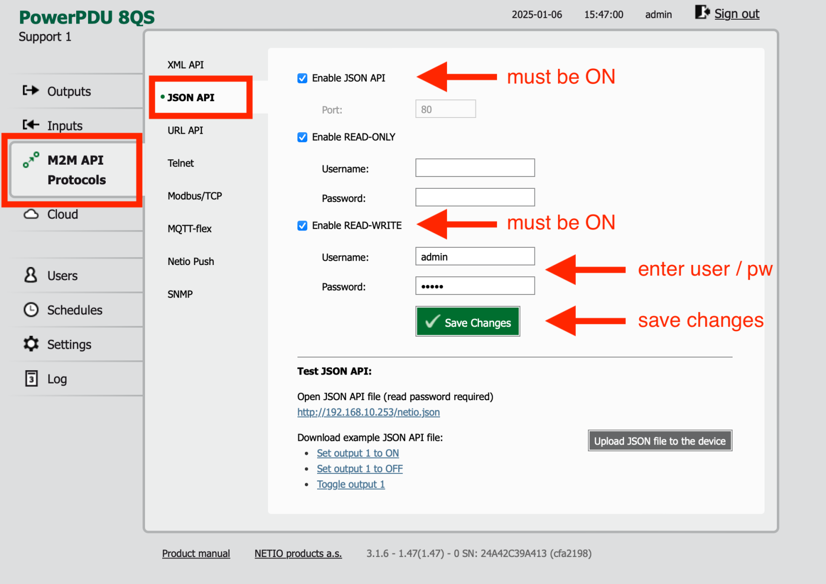](https://wiki.skaarhoj.com/uploads/images/gallery/2025-01/netio-webui-enable-readwrite.png)
# OBS Studio 28+
OBS Studio 28.0.0 and newer have obs-websocket support included in the firmware, so there is not need for downloading an additional support file for OBS. However, if you are using an older version of OBS Studio, please make sure you have downloaded the proper websocket support for your computer running OBS: [https://github.com/obsproject/obs-websocket](https://github.com/obsproject/obs-websocket)
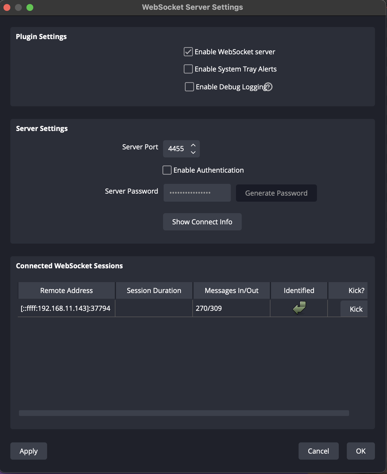
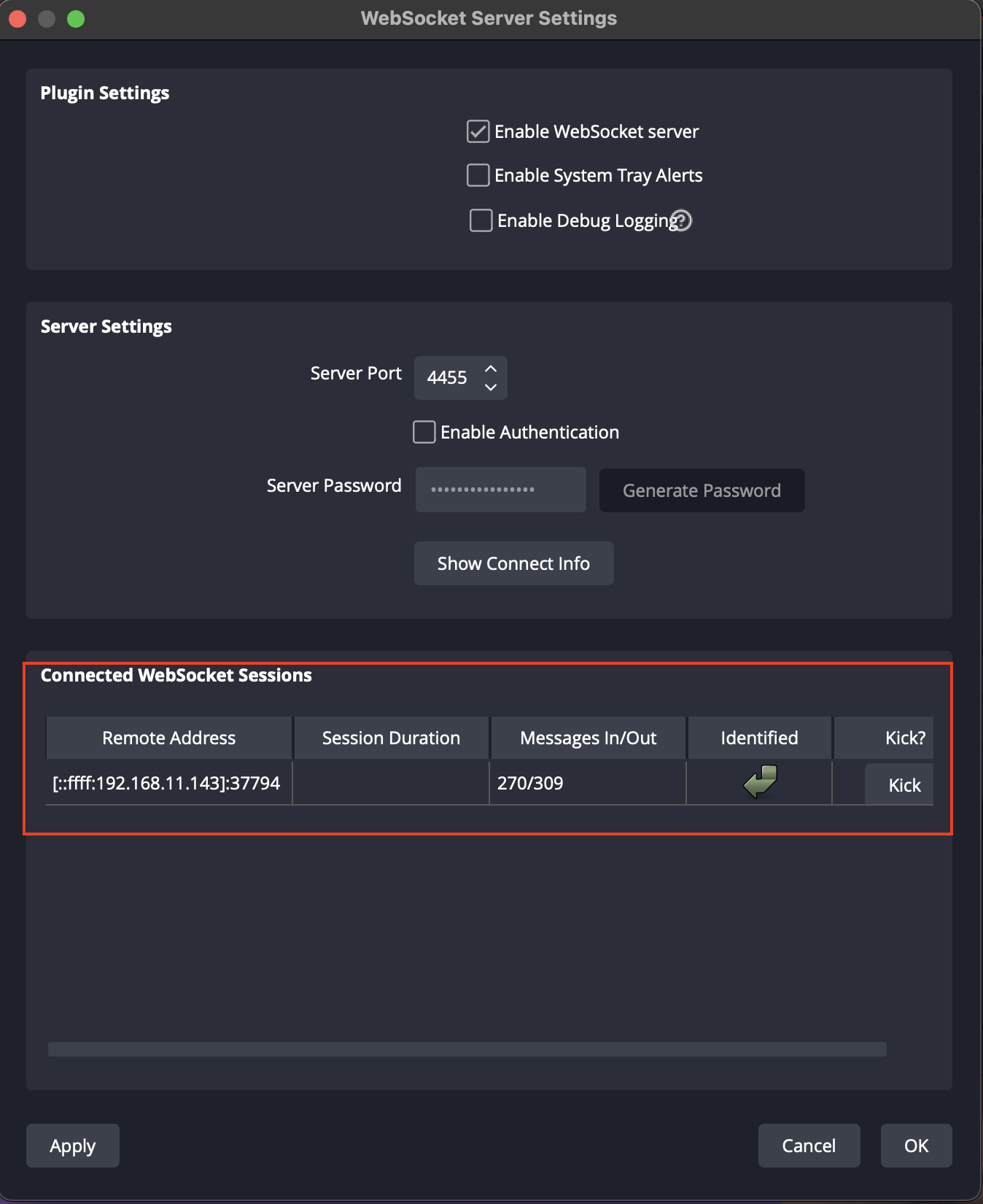
**OBS Studio Settings**
Within OBS Studio there are a few settings to configure under Tools/WebSocket Server Settings
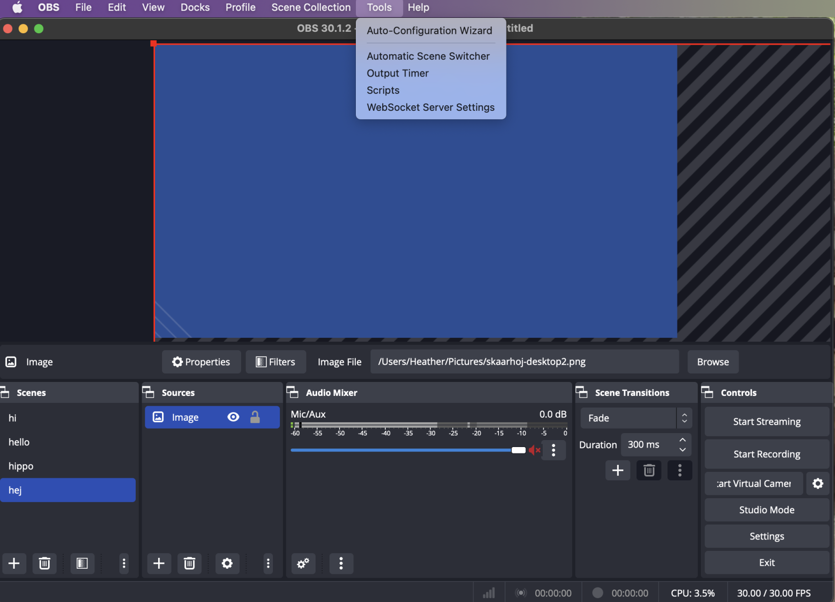
1. Under Plugin Settings, Enable WebSocket Server.
2. Under Server Settings, set the Server Port number (the default port is fine, just make note of the port number)
3. Also under Server Settings, Enable Authentication if desired and set Server Password if desired.
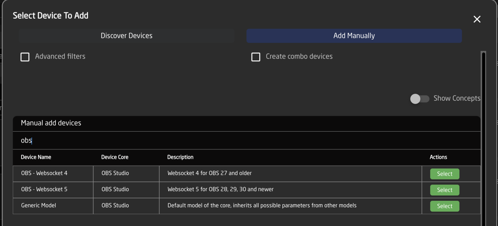
**Skaarhoj Device Settings**
On the Home Page, add OBS as a device manually. For OBS Studio 28 and newer, select Websocket 5.
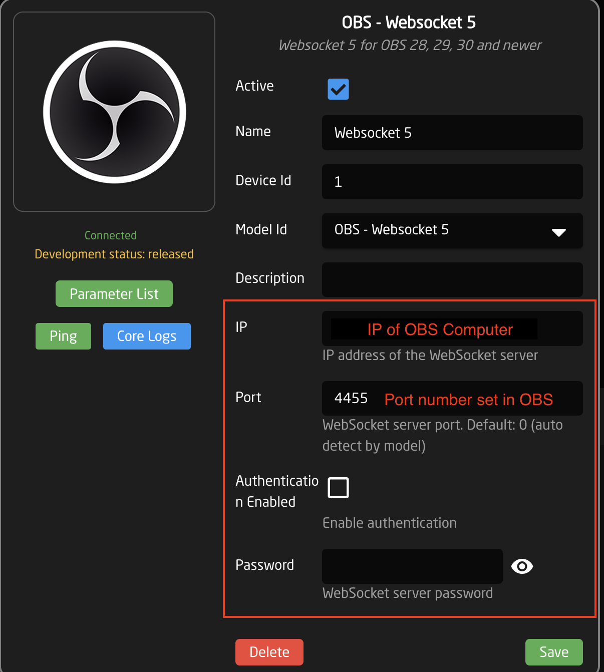
Within the device details:
1. Input the IP address of the OBS computer
2. Input the Port number set in the OBS Websocket Server Settings
3. Select Authentication Enabled if you enabled it in OBS
4. Input password if you set one in OBS
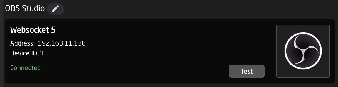
**Confirm Connection**
Once the information has been input, there should be a green Connected status in the device details on the Skaarhoj Home page.
[](https://wiki.skaarhoj.com/uploads/images/gallery/2024-06/screenshot-2024-06-04-at-11-30-49-am.png)
Within the WebSocket Server Settings in OBS, you should also see the IP address for your Skaarhoj panel under the Connected WebSocket Sessions.
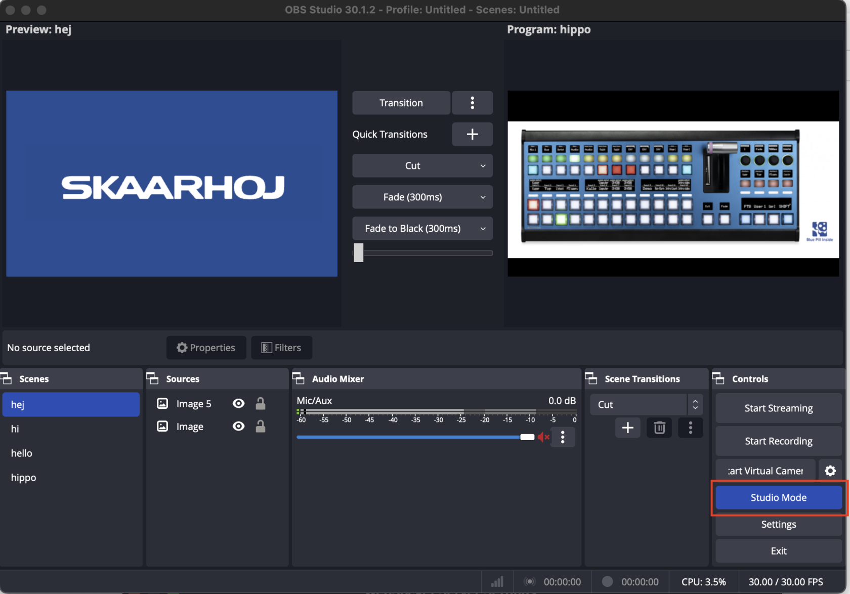
**Additional Information**
By default, Preview selections with not work within OBS unless you have selected Studio Mode. Once selected, Preview and Program will work as expected.
[](https://wiki.skaarhoj.com/uploads/images/gallery/2024-06/screenshot-2024-06-04-at-11-21-14-am.png)
# Panasonic Lumix
**Tether**
The Panasonic Lumix only allows 1 network connected client at a time. This means it is not possible to use both Panasonic's Tether interface and a Skaarhoj panel simultaneously.
**Password**
Connectivity to the Panasonic Lumix requires a password. Due to the way the password is usually set in the Lumix, it can be necessary to connect with the Lumix set to the default password: **FGHIJ67890**
The password needs to be entered in the Device Details section for each connected Lumix camera.
**[](https://wiki.skaarhoj.com/uploads/images/gallery/2022-08/lumix.png)**
**Connectivity Issues**
If you encounter connection issues despite all settings appearing correct, we advise performing a factory reset on the camera and using the default password. Crucially, after resetting, avoid connecting the camera with the Lumix Tether application, as it might lock in the camera somehow and thereby prevent the SKAARHOJ device from connecting. The exact cause is unclear, but this solution has been effective for other users.
# Panasonic RP150 Controller Setup
# Producer Assistant - Video Follow Audio
The Video Follow Audio model of the Skaarhoj Producer Assistant core, provides functionalities for automated switcher control, based on logic inputs, such as an audio meter.
This can be used in simple scenarios, such as a debate or radio program, to automatically cut to a camera on the person speaking.
This is an advanced topic. To configure the system, knowledge of Skaarhoj Device Core parameters and IO References is expected.
### How it works
The Video Follow Audio system, works by monitoring a device core parameter for each person (called participants) in the system. It checks periodically if a new participant is talking more than others, and then cuts to that participant. If the person have been talking for a long time, it will periodically cut to a wide shot (if setup) or the participant previously on as a listening shot.
### Requirements
For the system to work, it requires an input parameter for each participant. This will often be an audio meter for the mic the participant is using.
Not all devices provides the same quality of audio meters. Some have a slow update rate, some have a high latency and some are not too precise. This means that though it might work in theory, some parameters are less than ideal for reliable switcher control. If possible, please try it out before you buy the license.
### Configuration
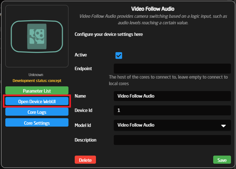
To use the Video Follow Audio system, some initial setup has to be done in the device WebUI. In the device configuration menu
Most of the configuration happens in the Device WebUI. To open it, open the device configuration of the home page of Reactor, and press 'Open Device WebUI'. It can also be found in the packages menu.
[](https://wiki.skaarhoj.com/uploads/images/gallery/2025-06/CgBimage.png)
The configuration page consists of 3 parts.
When you are finished editing the configuration, remember to press save on the bottom of the page! This will trigger a restart of the system.
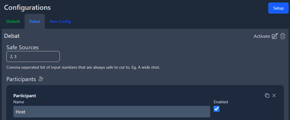
#### Configurations
The main page provides a tab list, with different configurations. This provides a way to setup different configurations, that can quickly be changed between.
[](https://wiki.skaarhoj.com/uploads/images/gallery/2025-08/image.png)
#### Switcher & PTZ Setup
In the top right corner of the configuration page, a setup button is located. This is where the global setup for all configurations are done. This is where the switcher and PTZ cameras are setup.
[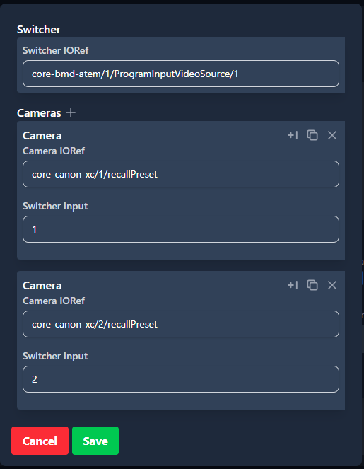](https://wiki.skaarhoj.com/uploads/images/gallery/2025-08/WtSimage.png)
This page provides the main parameter for controlling the switcher. In this case it is using a Atem switcher and controlling the Program Input Video Source parameter.
##### PTZ Cameras
PTZ Cameras can be used to film specific participants, so you don't need a fixed shot on each person. Multiple cameras can be configured. Each camera has an IOReference for how to recall presets and a switcher input number.
In this case we have two Canon Camera using the Canon-XC core. The camera with device index 1 is found on the first input of the switcher and the camera with device index 2 is found on the second.
### Configuration
Each configuration consists of a number of participants with specific actions. It is also possible to provide Safe Sources. These are input numbers with cameras that can also be cut to, for example a wide or audience shot.
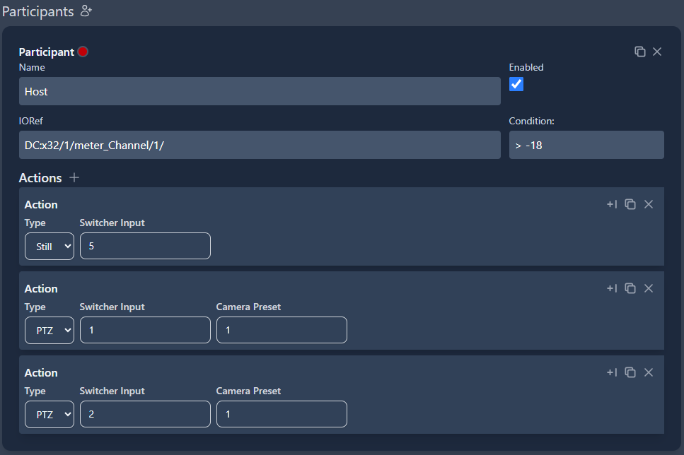
#### Participants
This is where you setup each participant in the system. A participant will need at least a input reference with a logic statement and an action. A small tally indicator is also shown for each participant. A participant can also be enabled or disabled.
[](https://wiki.skaarhoj.com/uploads/images/gallery/2025-08/hm4image.png)
##### Input reference
Each participant have a IO Reference for how the system will read if the participant is talking or not. In most cases this will be an audio meter. They can also have a condition setup. This uses standard logic signs to express how the IO Reference should be checked.
In this example, the IO Reference is a channel meter from a Behringer X32 audio mixer, and the participant will be assumed to be speaking, every time the channel meter is over -18.
##### Actions
Each participant will need one or more actions to be configured. An action can be either a still camera or a PTZ camera. Both types would need a Switcher Input to specify what source the switcher should cut too. A PTZ camera will also require a preset number, to know what preset to recall, before the camera is selected.
In this example, the participant has both a still camera and two PTZ camera configured, so the system will pick a random of the three.
A PTZ action needs to have a camera configured in the 'PTZ Cameras' section with a matching switcher input for it to work. If a participant only have PTZ cameras configured, the system will try to use a camera that is not currently live. If only the live camera can be used, the system will try to cut to a safe source, before recalling the preset.
When the configuration have been changed, remember to save it manually in the bottom of the page.
# Protocol-OSC
Open Sound Control (OSC) is a widely used protocol for controlling all sorts of devices. This is a generic protocol implementation, so you have to know the exact commands your device reacts to, and how to connect to it.
OSC works by sending commands with an address and often also an argument. An example: To control 'level' on a device, the command could look like this:
• Address: *'/level/1'* • Argument: *'1.5'*
Most OSC commands use slashes in the address to divide the address into fields. The address above, *'/level/1'*, could specify that we want to control the level parameter on channel number 1.
These addresses need to be known beforehand, and can often be found in the manual or the OSC specification for the device.
At the moment our OSC device core only works via UDP. This is the standard for most OSC devices, but a few use TCP.
### Configuration
To configure the device you need to set some device specific information.
[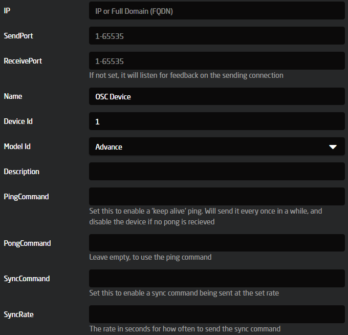](https://wiki.skaarhoj.com/uploads/images/gallery/2023-09/uqoimage.png)
- IP
Set the IP address of the device to control
- Send Port
Set the port to send OSC commands to. This can either be set on the device or found in the manual.
- Receive Port
Set the port to listen for OSC commands. Some devices send the return commands to the port they receive commands from. If this is the case, then leave it empty, otherwise set the port specified on the device or found in the manual.
- Ping Command
To check if the device is connected and active, you can specify a command to send once in a while. If we receive a response, we expect the device to be connected. This is often something like "/Ping" or "/KeepAlive".
If the Ping Command is not set, the device status will always be connected, since there is no way of knowing if there is a device listening.
- Pong Command
On some devices, the response to the Ping Command is different from the command sent. For instance, some devices will respond with "/Pong" when a "/Ping" is sent. Specify it here, or leave it empty to use the Ping Command.
- Sync Command
Some devices need to receive a sync command once in a while to keep sending feedback. This can be left empty.
- Sync Rate
Set how often the Sync Command should be sent. In seconds.
### Models
The OSC core provides 3 different models to use:
**1. Simple model**
This model includes parameters for very simple one way OSC control.
A control parameter has to be specified with a few meta parameters.
[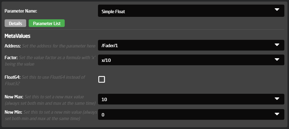](https://wiki.skaarhoj.com/uploads/images/gallery/2023-09/A2yimage.png)
- Address: This is the address to send the command to.
Type specific meta parameters.
- New Max: This specifies the max of the range for float and integer parameters.
- New Min: This specifies the min of the range for float and integer parameters.
- Float64: OSC can send both Float32 and Float64 arguments. The default is Float32 but set this to use Float64.
- Factor: Float commands can have a factor applied before being sent. For instance some faders go between -90 to 10, but the argument sent needs to be between 0-1. A factor can be specified to do this. Set 'x' as the value and write the math needed. For instance '(x+90)/100'.
- As Integer: For Bool commands it can either be sent with an argument of 'true' or 'false', or as an integer with value 1 or 0.
- Invert: Bool commands can be inverted when sent.
**2. Dynamic model**
This model includes everything from the simple model, but also a way to receive feedback on parameters.
Each parameter has a number of dimensions. These dimensions are assigned different commands, that then can be controlled, or could listen to feedback.
**3. Advanced model**
This model includes everything from both the simple and dynamic model, but also a way to set up multiple dimensions of a parameter. For instance if you have many faders to control, you only have to configure it one time, and it will auto populate the second dimension of control.
The main difference is that when setting the address or feedback, a string formatter can be used. For instance if you have 20 level commands ('/Level/1', '/Level/2', '/Level/n'...). Instead of setting them up one by one, the Address can be set to '/Level/%d', and then the Count meta parameter set to 20. Now the parameter will be populated with 20 sub dimensions to control, one for each level control.
Some devices will need leading zeros, for instance '/Level/01'. To set this, use '/Level/%02d'. That will make it a width of 2 and pad it with zeros.
### The web UI
The easier way to set up the dynamic and advanced control parameters is through the web UI. To open it, a dynamic or advanced model needs to be configured. Open Reactor and navigate to the 'Packages' menu. Here you can find the osc package, and a button to open the UI.
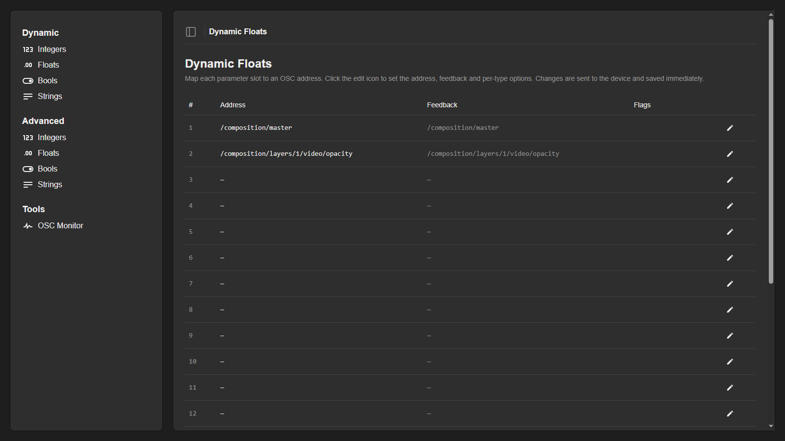
The sidebar on the left contains a section for each model kind: 'Dynamic' and, when an advanced model is configured, 'Advanced'. Each section has a page per data type: Integers, Floats, Bools and Strings. If more than one OSC device is configured, a device selector appears at the bottom of the sidebar.
Each page shows a table with one row per parameter slot, listing the configured address, the feedback address and a few flags. Click the pencil icon on a row to open the editor for that slot.
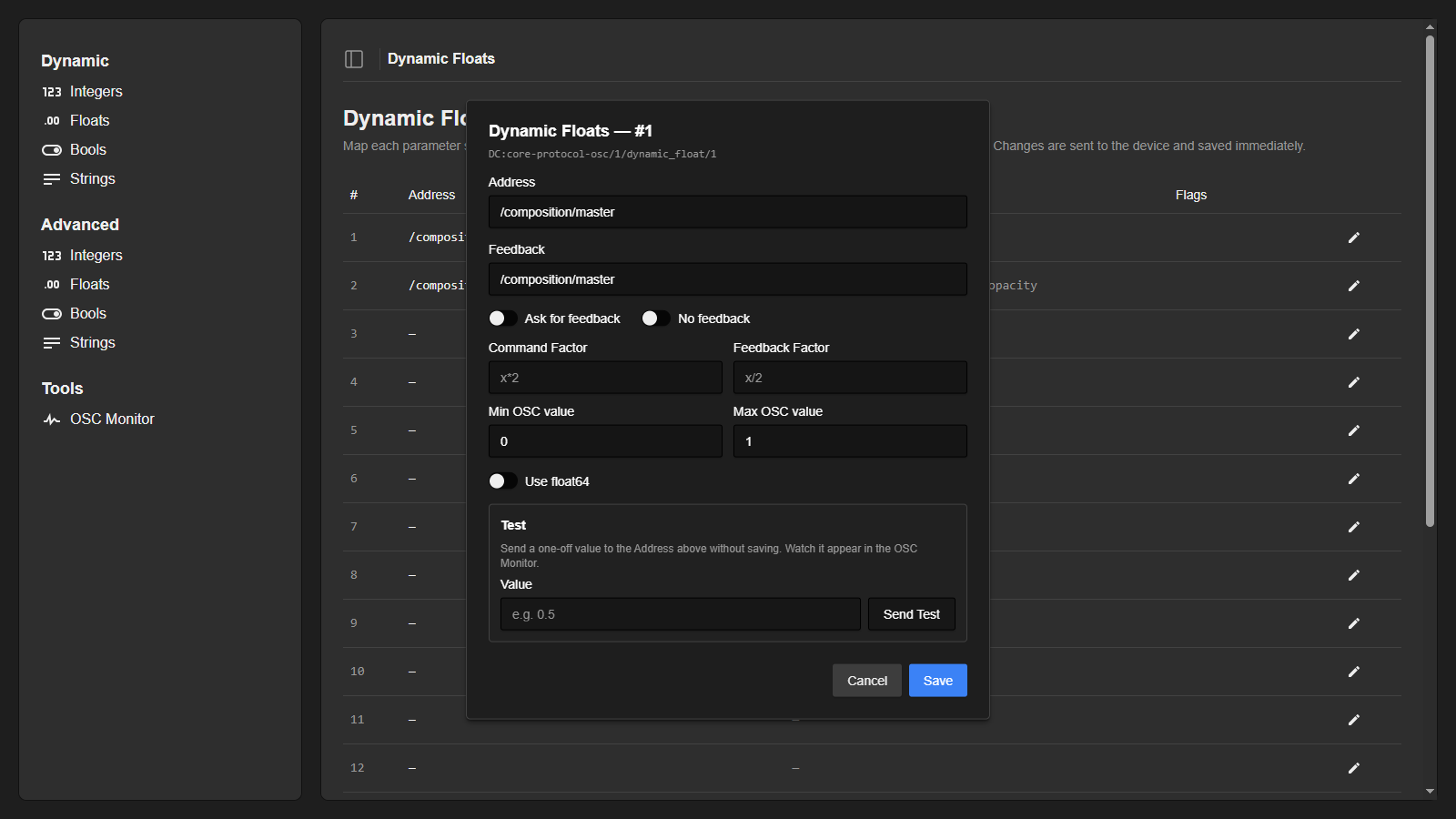
The editor contains everything needed to set up a command. The same settings are also available through the config parameter of each type, for setups where the UI is not used.
- Address: The OSC address commands are sent to. Leave it blank to make a slot that only listens for feedback.
- Feedback: Some devices have a different address for feedback compared to the control address. Specify it here, or leave it blank to use the Address.
- Ask for feedback: Some devices won't reply to a command, but need to receive the address without an argument to return the current value. Enable this to request values that way.
- No feedback: If the device does not return feedback for this parameter, enable this.
- Command Factor / Feedback Factor (integers and floats): Math applied to the value before it is sent, and after it is received. Set 'x' as the value and write the math needed, for instance '(x+90)/100'. The two factors need to be each other's inverse: if the Command Factor is 'x\*10', the Feedback Factor needs to be 'x/10'.
- Min OSC value / Max OSC value (integers and floats): The range of the value as it is sent on the wire, that is after the Command Factor has been applied. The range of the control itself is calculated automatically by running these limits through the Feedback Factor.
- Count (advanced types only): How many sub dimensions to populate from the address formatter, as described under the advanced model.
- Type switches: Per type alternative encodings. 'Use float64' for floats, 'Use int64' for integers, and 'Use int (0/1) instead of bool' for devices that expect 1 or 0 instead of 'true' or 'false'.
The Test box at the bottom of the editor sends a one-off value to the address in the dialog, without saving anything. This is useful for trying out an address found in a manual before committing to it. Clicking Save sends the configuration to the device and stores it immediately.
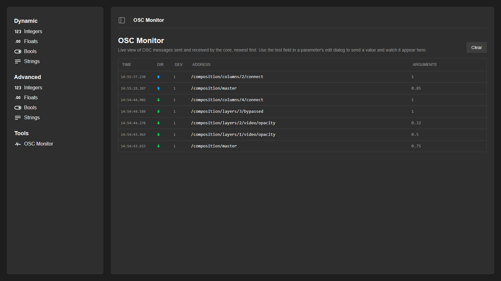
**OSC Monitor**
Under the 'Tools' section in the sidebar, the OSC Monitor shows a live view of the OSC messages the core sends and receives, newest first, with the direction, device, address and arguments of each message. Combined with the test field in the editor, this makes it easy to debug an address that does not respond as expected, or to discover the addresses a device sends out when it is operated directly.
Example: Resolume Arena
Resolume is a popular VJ application with a well documented OSC implementation. The full address list can be found in the [Resolume manual](https://resolume.com/support/en/osc), and the exact address of any control can be seen in Resolume itself via Shortcuts > Edit OSC.
Resolume listens for OSC on UDP port 7000 by default (Preferences > OSC). So in the device configuration, the IP is set to the machine running Resolume and the Send Port to 7000.
To get feedback, enable OSC Output in the same preferences panel, point it at the IP of the SKAARHOJ panel and pick an outgoing port, for instance 7001. Set the same port as the Receive Port in the device configuration. Finally, select the 'Output All OSC Messages' preset under Shortcuts > Edit OSC, so Resolume sends out everything that changes in its interface.
Resolume's continuous parameters are floats from 0.0 to 1.0, so no factors are needed, and layers and clips are numbered from 1 without leading zeros.
**Composition master through dynamic floats**
The composition master fader has a single fixed address, so it fits a dynamic float: Address '/composition/master', Min OSC value 0, Max OSC value 1. The first screenshots on this page show this setup.
**Layer opacity through advanced floats**
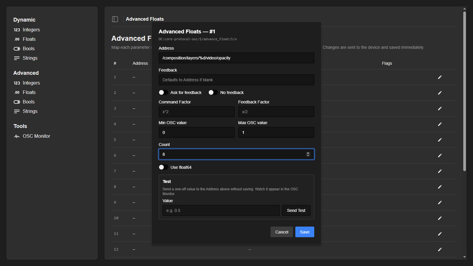
The opacity of all layers is set up in one go with the address '/composition/layers/%d/video/opacity' and the Count set to the number of layers in the composition, here 8. Since Resolume layer numbers have no leading zeros, the plain '%d' formatter is used. The OSC range is 0 to 1 with no factors.
**Layer bypass through advanced bools**
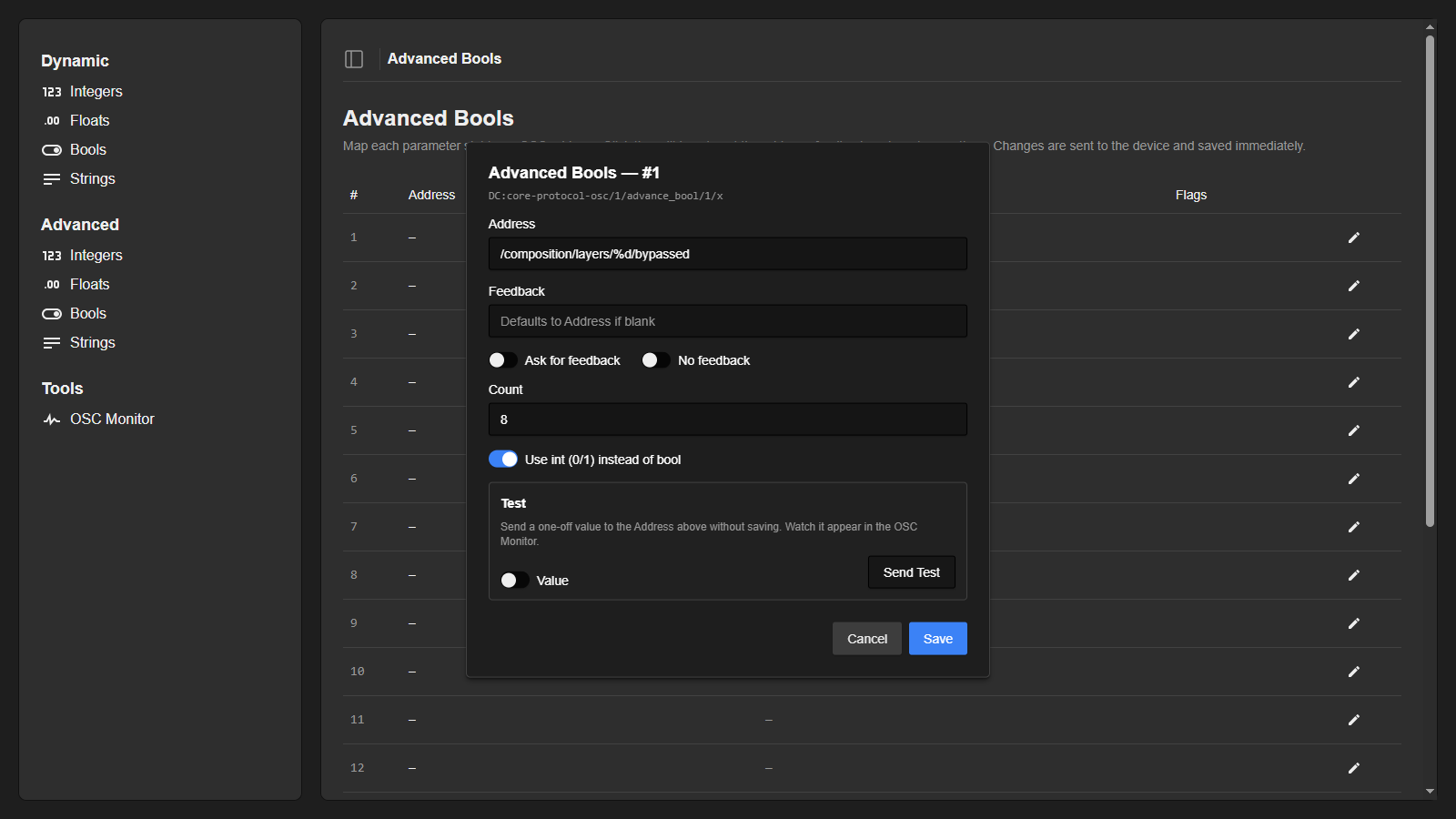
'/composition/layers/%d/bypassed' toggles a layer on or off. Resolume expects an integer of 1 or 0 rather than a 'true' or 'false' value, so 'Use int (0/1) instead of bool' is enabled.
Example: 12 channel audio mixer
As an example, let's say we want to control a simple audio mixer with 12 channels. From the manual, we find the following OSC parameters we want to control:
Fader control - a 0 to 1 float with the address '/mixer/level/x'. The x marks the channel number from 01-12.
Mute control - a 0 or 1 integer with the address '/mixer/mute/x'.
Pan control - a -100 to 100 integer with the address '/mixer/pan/x'.
In the manual, we also see that in order to get a current value from the device, we can send the address without a value, and it will return the current value.
Since we have multiple channels for each command, we will use an advanced model.
To set up each command, we open the UI as described earlier and configure one slot on each of the advanced pages.
**Fader control through floats** 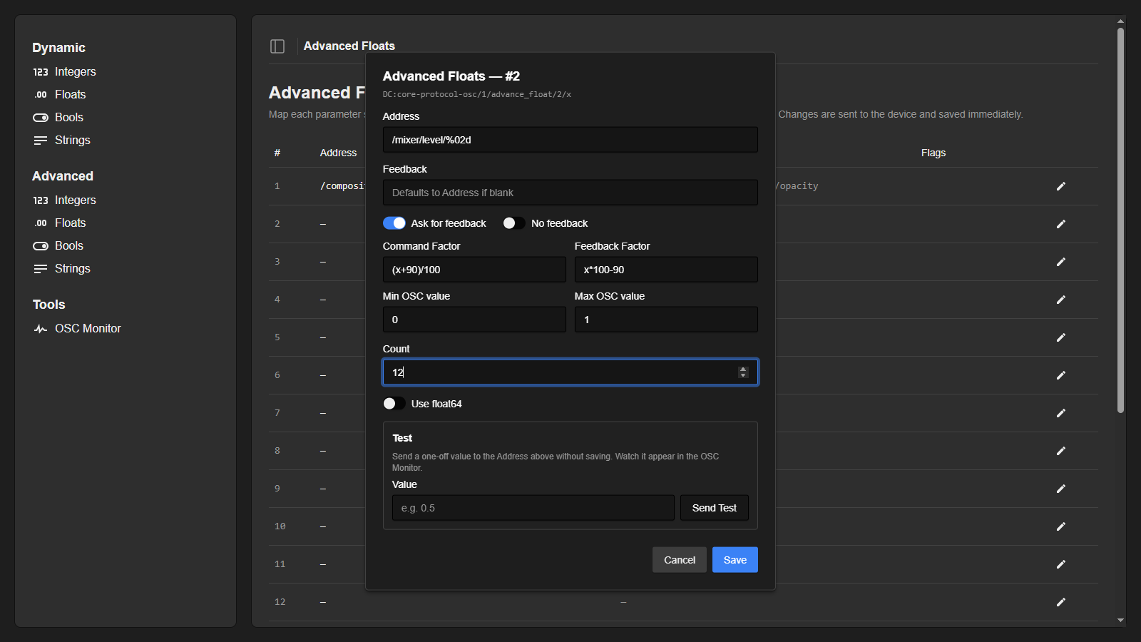
Here the last part of the address is set up as %02d. This is a string formatter that will take the channel number and insert it as a number with a width of 2 padded with zeros. E.g. channel 1 would be: '/mixer/level/01'.
The feedback is left empty, and will then default to the same as the address.
Ask for feedback is enabled, since we can get the current value by asking for it.
From the manual, we know the fader on the device goes from -90dB to 10dB, but the float sent over OSC needs to be from 0 to 1. The Command Factor '(x+90)/100' converts the dB value to the OSC value, and the Feedback Factor 'x\*100-90' converts it back.
The Min and Max OSC values are set to 0 and 1, since that is the range actually sent on the wire. The core derives the -90 to 10 control range automatically from the Feedback Factor.
Finally we set the Count to 12, since that is the amount of channels we want to control.
**Mute control through bools sent as integers**
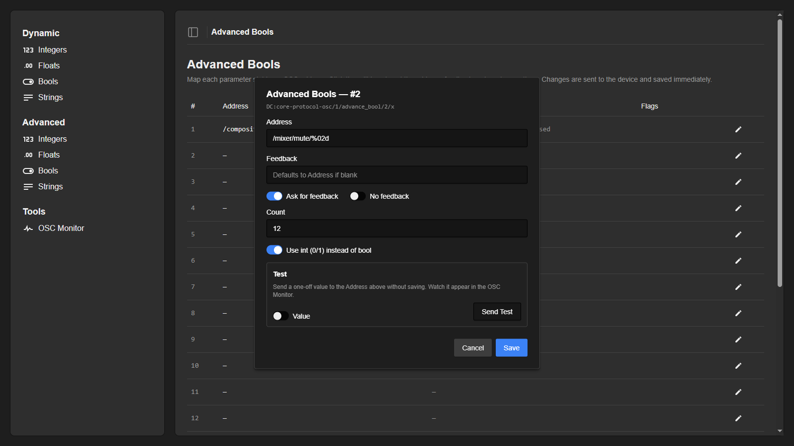
Most things are set up as above. Since the mixer wants an integer of 0 or 1 instead of 'true' or 'false' values, 'Use int (0/1) instead of bool' is enabled.
**Pan control through integers** 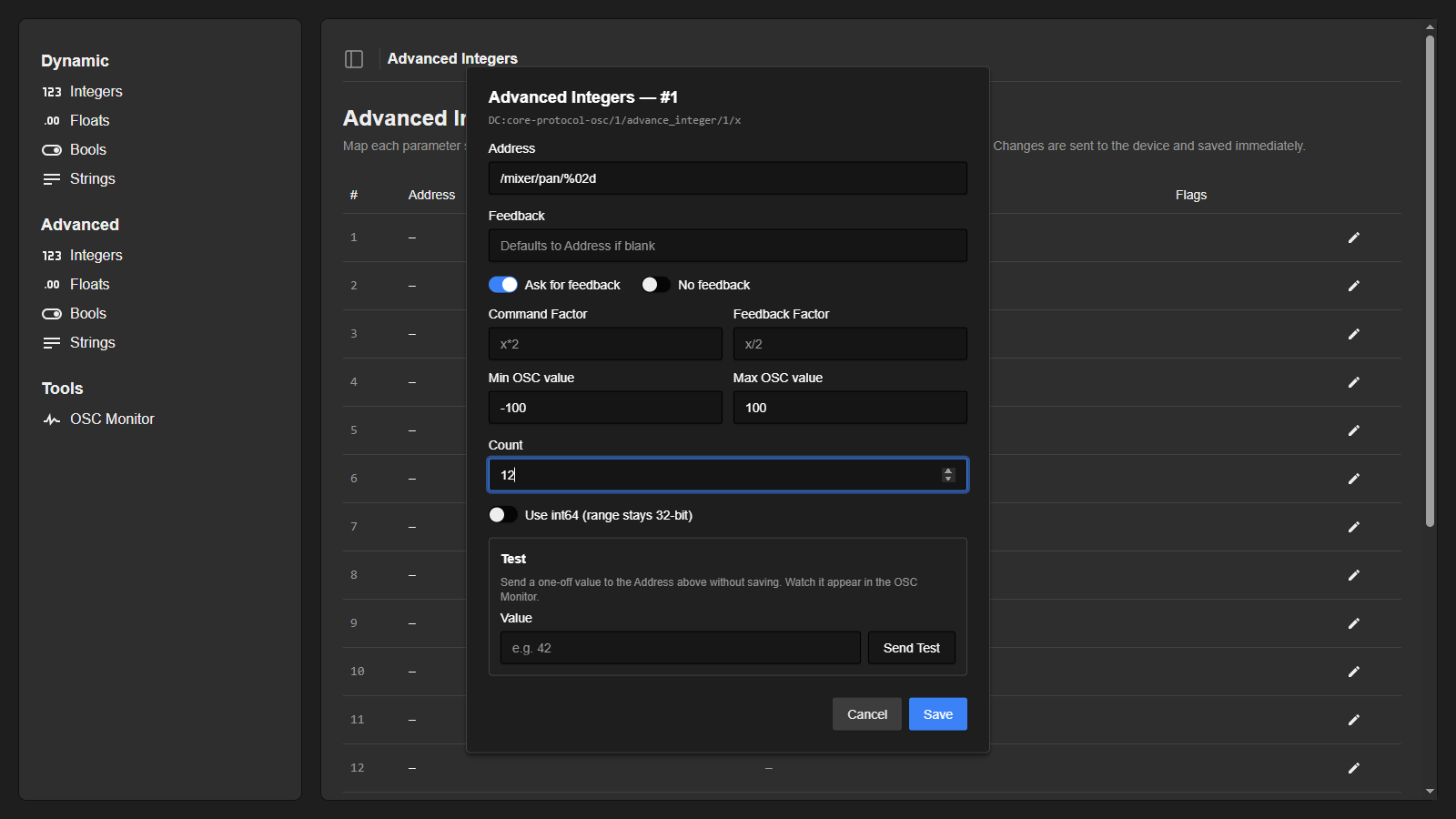
Again, many of the things are the same as above. The Min and Max OSC values are now set directly to -100 and 100, with no factors. This will send the raw value from -100 to 100.
# PTZ Trace on Blue Pill
PTZ Trace is a feature that simulates the operation of a PTZ (pan-tilt-zoom) camera using pre-recorded speed commands, as if a joystick is controlling it. The commands are usually recorded from an operator who previously maneuvered the camera's pan, tilt, and zoom axes with a joystick.
SKAARHOJ controllers that control VISCA cameras, as well as Panasonic, Canon XC protocol, Vaddio, and Sony's newer PTZ protocol through websockets, incorporate the PTZ Trace functionality as of IBC 2023.
### Features
- Each trace has a linked preset bank. Typically, a camera will have 16 to 100 preset banks.
- Maximum of 10 minutes recording time as a safety limit.
- Unlimited speed steps.
- Ability to record and playback Pan, Tilt, and Zoom axes.
- Supports looped playback and ping-pong mode (reverse playback after reaching the end of the trace).
- Allows insertion of user-wait commands during recording.
- Provides individual end wait times for looped modes.
- Recorded into the device core data space and stored between reboots.
### How to use it
PTZ Trace is built into our default configurations and is accessible through the preset recall buttons. To start recording a trace, press and hold the preset button for 3 seconds. After one second, a stationary preset will be recorded, but if you continue to hold down the button for a total of 3 seconds, the button will light up red and the display will indicate "Recording". At this stage, use the joystick to maneuver the camera, and press the same button again to stop the recording.
Once a trace is saved on a preset button, the button turns blue. Pressing the button once arms the trace (amber button color), which recalls the associated preset and positions the camera at the start of the trace. Pressing the button again will commence the playback (green button color) with the display showing a countdown timer.
Trace is built-into our pre-made PTZ configurations - but its not enabled as default. You can enable/disable Trace in the Engineering menu for the configuration. You can see how to access the Engineering menu for the various panel configurations here: https://wiki.skaarhoj.com/books/blue-pill-reactor/page/engineering-menu
Note: Features such as looping, ping-pong mode, wait times, and user waits are not yet integrated into the default configurations. We will update this documentation once these features become available.
You can manually assign Loop and Ping Pong to buttons in your configuration in the same way as any other parameter.
- goto Configuration page
- select an empty button -> now you see the commands list in the Inspector (window right side)
- open section for your camera -> select 'Choose other parameter'
- in parameter field, search for 'Trace Loop' or 'Trace Ping Pong' -> select the desired parameter
- finally, select 'Trace Preset number' -> click 'Submit' -> and confirm settings
(Both Camera and Preset number can, of course, be controlled by variables instead of a fixed numbers.)
### Support on cameras
Below you will find a table with preliminary indications of support on a number of tested camera models:
Notice: All cameras are capable of performing a meaningful trace playback, regardless of their ratings. A lower-rated camera can still deliver useful results. Please note that these are preliminary tests conducted under non-systematic conditions, primarily to assess the feasibility of the feature. We will provide updated and more comprehensive data in due course.
### Technical Notes
PTZ Trace in SKAARHOJ controllers works by replaying pre-recorded pan, tilt, and zoom speed commands to the camera. The accuracy of the playback depends on multiple factors:
- The response of the individual camera's motors to the same sequence of speed commands.
- The latency of the camera's processor.
- Network latency.
- The combination of axes, the number of speed command changes, and the degree of their change. More radical changes can result in greater errors.
- The level of zoom (greater zoom can lead to a worse perception of error).
#### Reverse playback (Ping-pong mode) issues
Most cameras tested perform exceptionally well on *forward* playback, meaning they tend to arrive at the same position consistently during playback. However, in *reverse* playback (ping-pong mode), substantial differences can be noticed on some cameras. This is due to some cameras interpreting pan and tilt speed commands differently based on the lens' focal length (zoom). Reverse playback essentially involves sending the same speed commands but in reverse order and with inverted polarity. Since a speed command may set the camera in motion differently depending on the current zoom position, reverse playback often ends up in a different place, particularly if zooming was utilized in the process. While it's usually beneficial for a PTZ camera to adjust its pan and tilt speed based on zoom position, it can hamper reverse playback.
On the SKAARHOJ device core side, we strive to play back all speed commands as accurately as possible. The offset from the original timing is typically less than 1ms. However, we must also respect the minimum time required between commands sent to a given camera. Despite this, our tests suggest that the timing precision we achieve is more than sufficient to provide extremely accurate playback.
# Raw Panel Device Core
The Blue Pill device core, *core-skaarhoj-rawpanel*, is used by an application like Reactor to forward parts of a connected panel to external Raw Panel clients while other parts are used by Reactor itself. This aligns with how Raw Panel is natively implemented on UniSketch controllers.
The idea can be understood by the drawing below:
[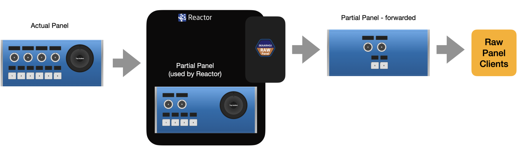](https://wiki.skaarhoj.com/uploads/images/gallery/2022-10/NTHimage.png)
The actual physical control panel connects to Reactor. The Raw Panel Device core is used to forward triggers from some hardware components to an external client. The rest of the panel is configured in reactor for any kind of use there.
To understand the alternative: panels can generally only be used with a single client, so either an external application or Reactor would have to be connected:
[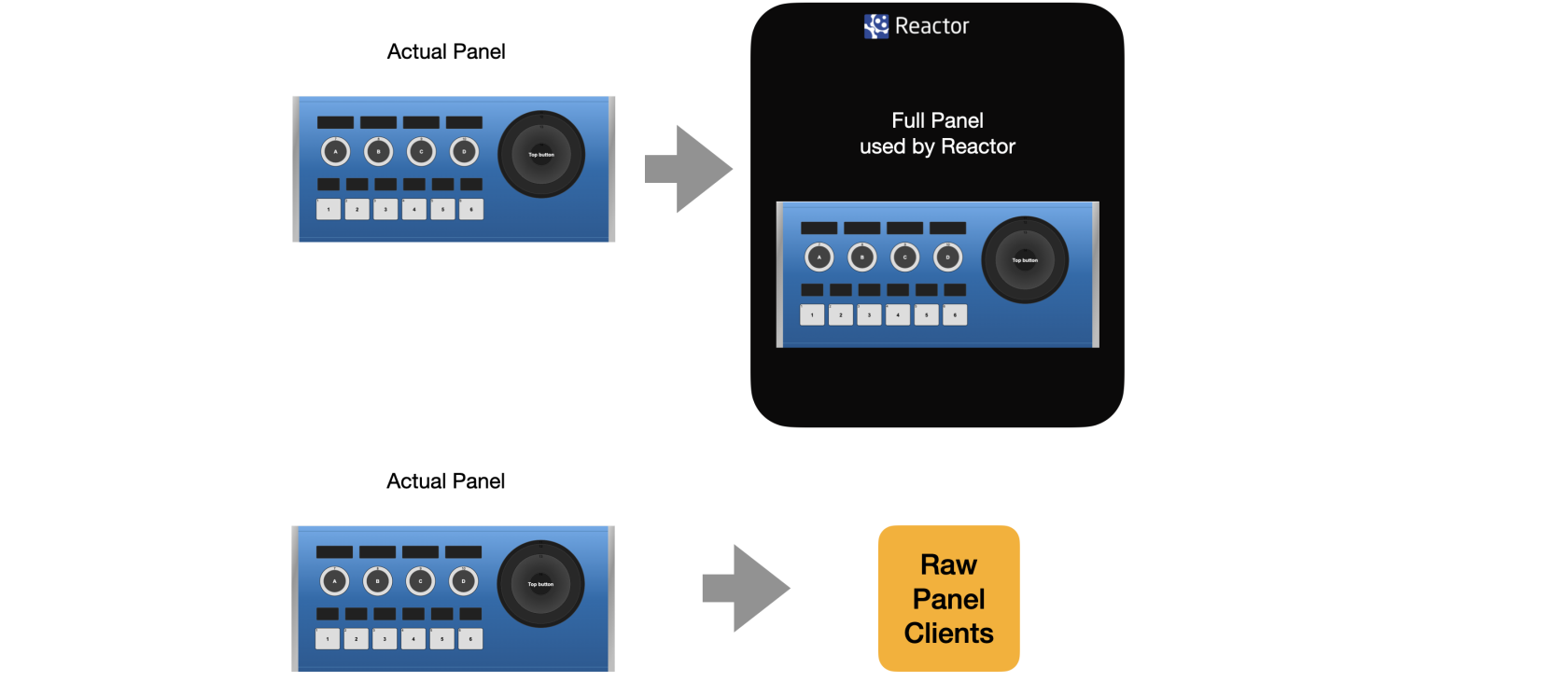](https://wiki.skaarhoj.com/uploads/images/gallery/2022-10/UZtimage.png)
### Configuration
Inside of Reactor there is an example configuration for the Raw Panel device core and a Rack Fusion Live. So, here is the basic project set up with the Raw Panel configuration selected for the Rack Fusion Live:
[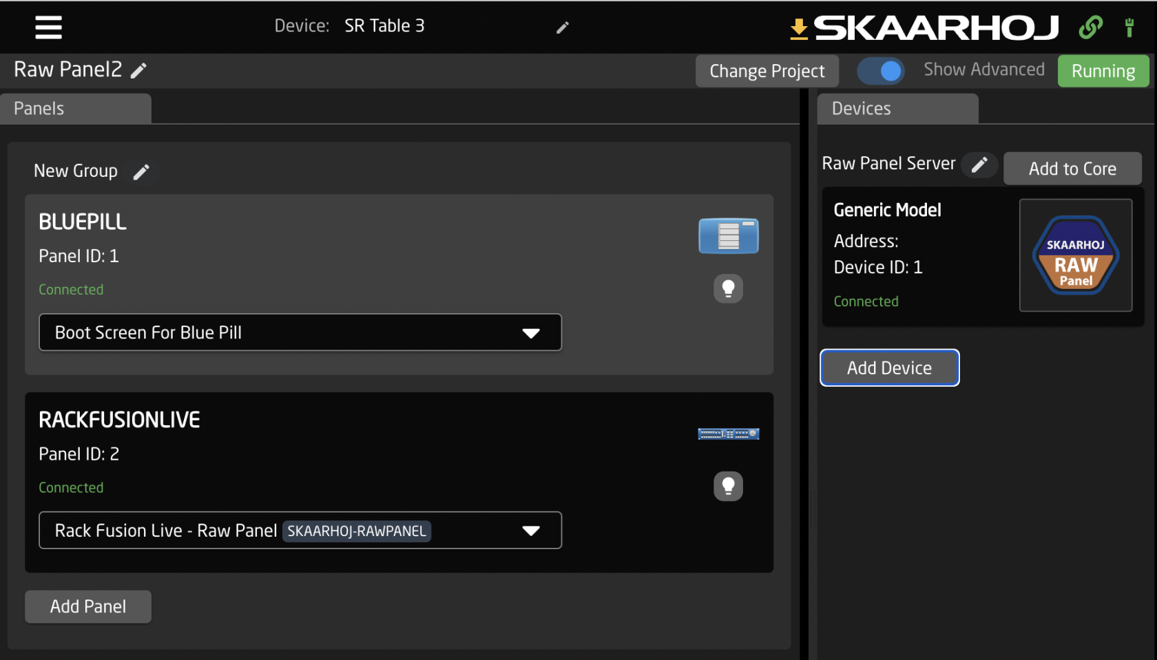](https://wiki.skaarhoj.com/uploads/images/gallery/2022-10/hYqimage.png)
The configuration for the Raw Panel device core looks like this:
[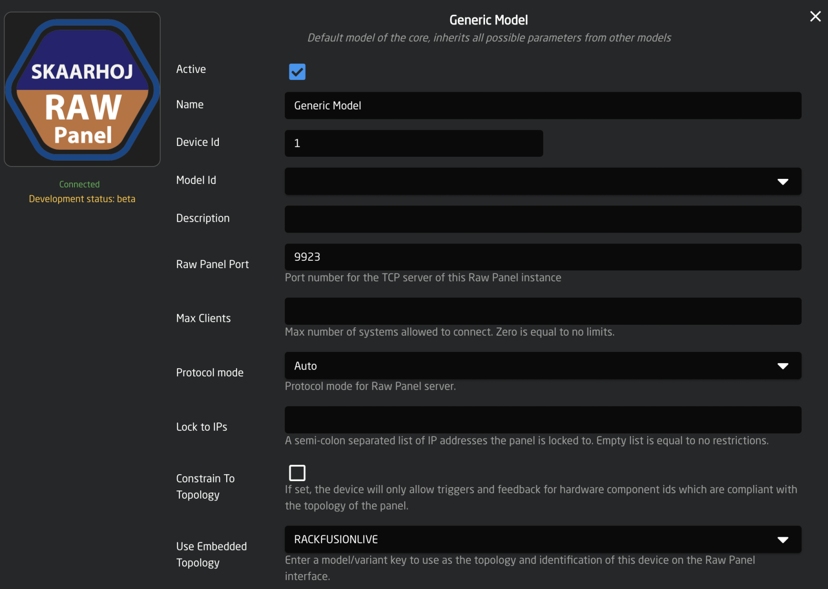](https://wiki.skaarhoj.com/uploads/images/gallery/2022-10/VV7image.png)
Most of this is default values, but one thing is super important: **Set the Use Embedded Topology to RACKFUSIONLIVE** (in this case). This is how the panel will report itself to connecting clients and it is highly likely that you want this topology to match the actual panel being used.
Now, with an application like Raw Panel Explorer you can scan the network for Raw Panels and connect to them for testing. When the application is started you will see panels on the network:
[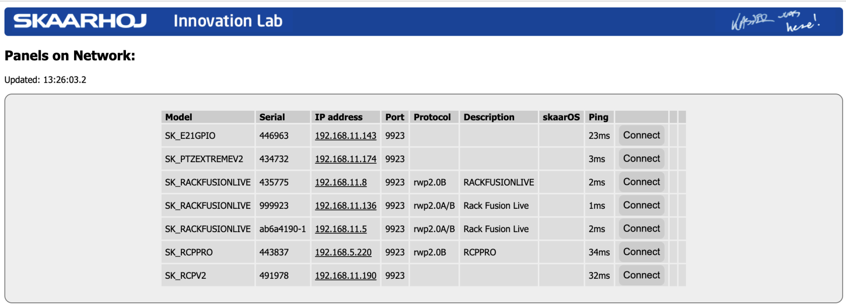](https://wiki.skaarhoj.com/uploads/images/gallery/2022-10/pOAimage.png)
Of interest is the fifth line where a Rack Fusion Live with serial ab6a4190-1 is found - that is our forwarded panel! The real panel that Reactor is connected to would be one of the other two panels (serial 435775 or 999923). If you connect to the forwarded panel it will look just like this:
[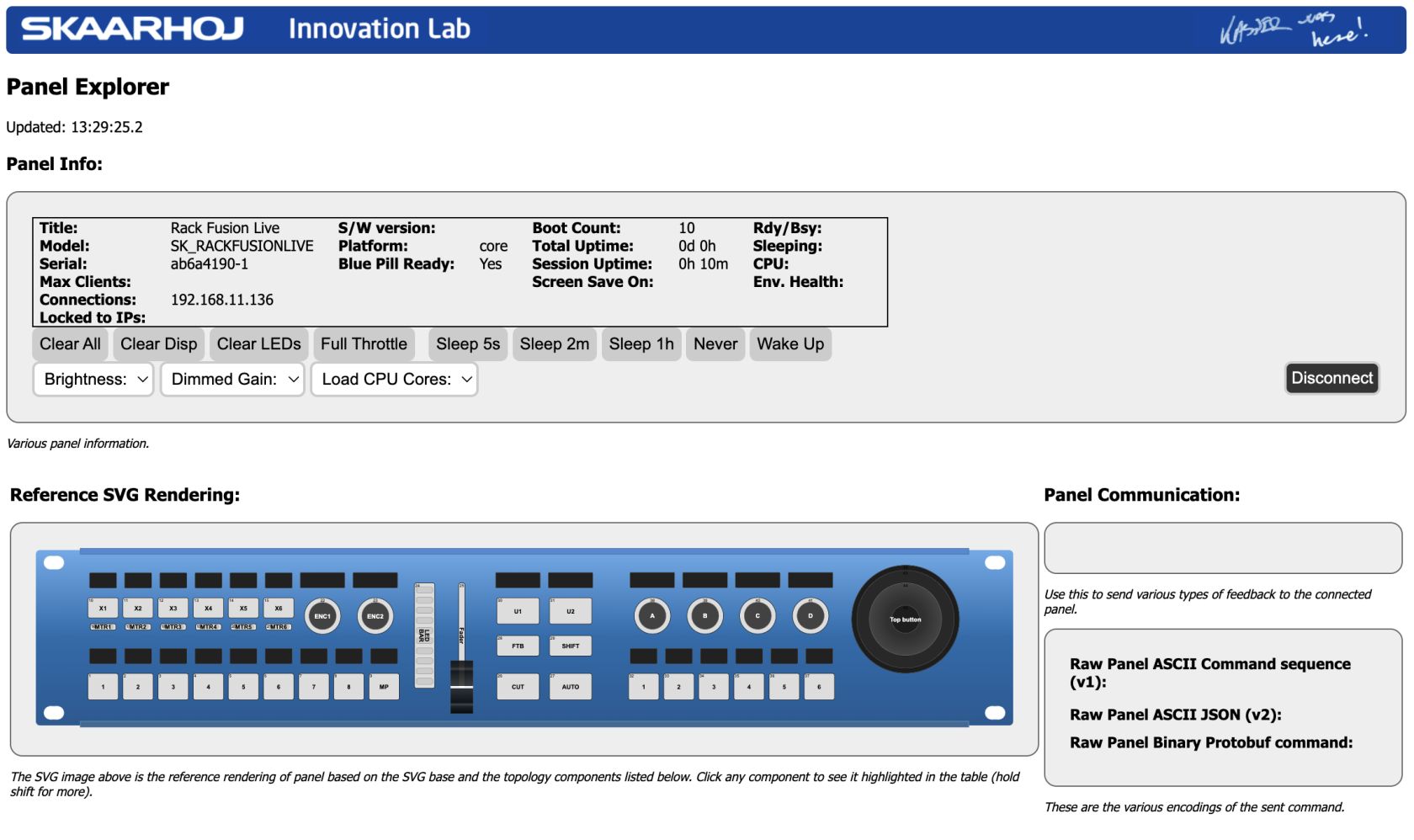](https://wiki.skaarhoj.com/uploads/images/gallery/2022-10/tg1image.png)
To the client it will look exactly like any Rack Fusion Live although its served via Reactor. However, the client won't know which hardware components is forwarded and which are not. It has to assume that the full panel is available.
### Configuration in Reactor
We should take a closer look at how the chosen configuration actually looks:
[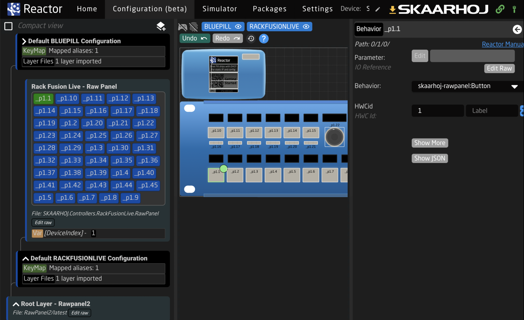](https://wiki.skaarhoj.com/uploads/images/gallery/2022-10/yDCimage.png)
In Reactor it's actually quite simple: For every hardware component on the panel (in the case of the picture above: component 1 = \_p1.1) a master behavior from the skaarhoj-rawpanel collection is added to each component. Here it's the "skaarhoj-rawpanel:Button" behavior with the constant "HWCid" set to 1. For encoders there would be a similar action:
[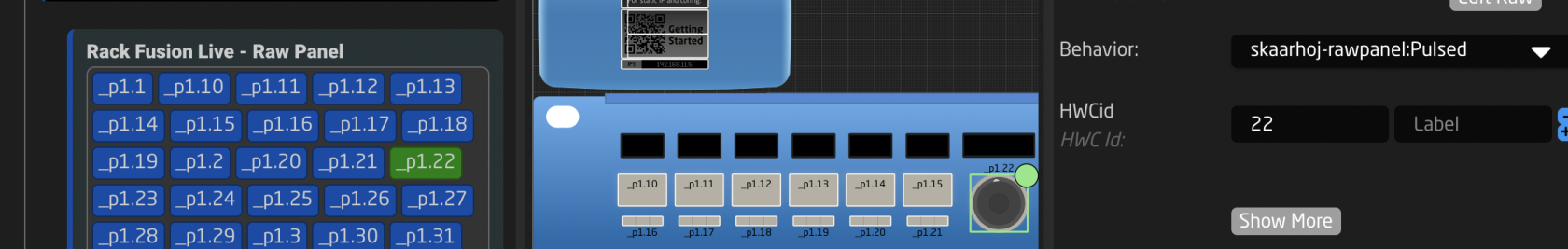](https://wiki.skaarhoj.com/uploads/images/gallery/2022-10/y0Yimage.png)
To achieve a mixed control scenario it's just a matter of combining this approach with other device cores, layers etc. in the usual way Reactor works.
#### Underlying JSON code
Here is a quick glimpse at the JSON code for the layer shown above:
[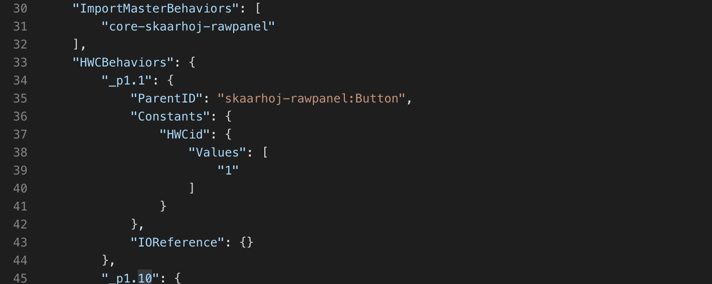](https://wiki.skaarhoj.com/uploads/images/gallery/2022-10/OGlimage.png)
(This is what you get if you click the tiny button *"Edit raw"* in a layer)
Lines 30-32 is actually really important - you have to import the "core-skaarhoj-rawpanel" library of master behaviors. Other than that you will find more of less the same setup for each hardware component like you see here for _p1.1. Just copy/paste this around.
### Device Core parameters
The device core parameters fall into two categories: Triggers and Feedback.
#### Triggers
Here are the triggers:
[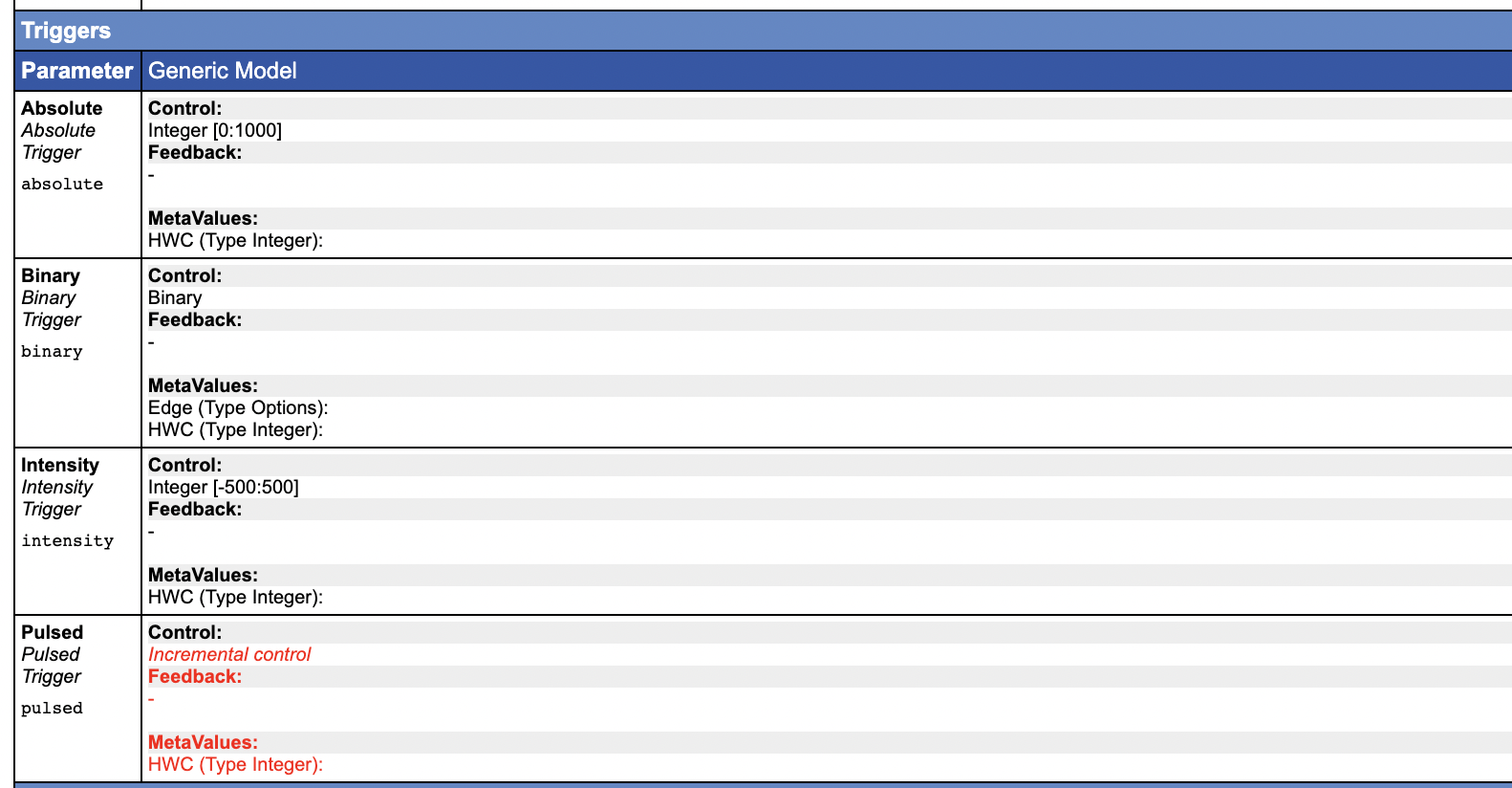](https://wiki.skaarhoj.com/uploads/images/gallery/2022-10/kWfimage.png)
It's probably not a surprise that there are four triggers: they correspond to the classic four trigger types that Raw Panel operates with:
- Binary triggers: Buttons and GPIO inputs
- Pulsed triggers: Encoders that send positive or negative values when turned
- Absolute triggers: Faders, T-bars and other analog components that stays in position
- Intensity triggers: Joysticks, shuttle wheels etc. that are analog but have a spring-loaded fall back to a center position.
#### Feedback
The feedback is also aligned with the Raw Panel protocol and more diverse:
[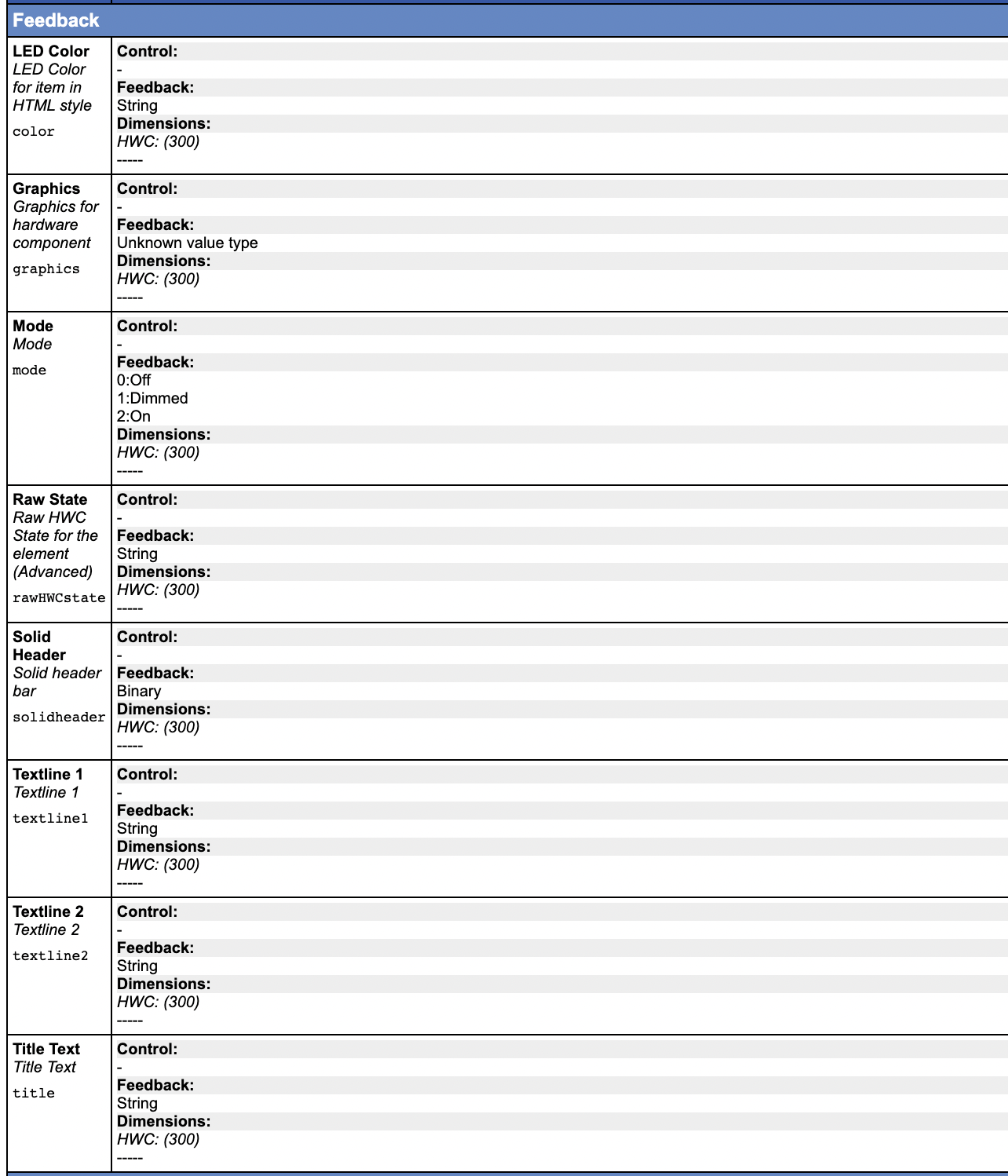](https://wiki.skaarhoj.com/uploads/images/gallery/2022-10/QUlimage.png)
- LED color is an HTML color code or a color index tag known from Raw Panel. This can be transferred directly to the ColorCode field in Reactor.
- Graphics is images if the client sends graphics over
- Mode is the On, Off and Dimmed states of components with LED feedback
- Title, Textline 1/2 and Solid Header are the four most basic elements that goes into rendering text on SKAARHOJ controllers.
- Finally, Raw State is a JSON string that contains the full feedback for all of the above, including finer details that has been left out.
The Raw State is available and meant to be used to transparently forward the state. This is most likely what you want to use while the others are more easy to mix and match and process further in Reactor if needed.
A deeper study into the configuration found in skaarhoj-rawpanel master behaviors will reveal more details and best practices on all of this.
### Mismatched Topologies
In case you choose a different Embedded Topology than the one that matches you panel - or if you try to send HWCid values that doesn't exist on a controller you will generally succeed. Reactor won't keep you from sending a button press for something the client thinks is a T-bar or non-existing. Unless you activate the setting Constrain to Topology setting in the device core configuration:
[](https://wiki.skaarhoj.com/uploads/images/gallery/2022-10/5T9image.png)
## Adhoc panels
Alternative to using a known SKAARHOJ topology you can also build an adhoc topology from ground up. If you keep the Use Embedded Topology field unset and enable Training mode, then a topology will be dynamically build up *as you send triggers to the panel*:
[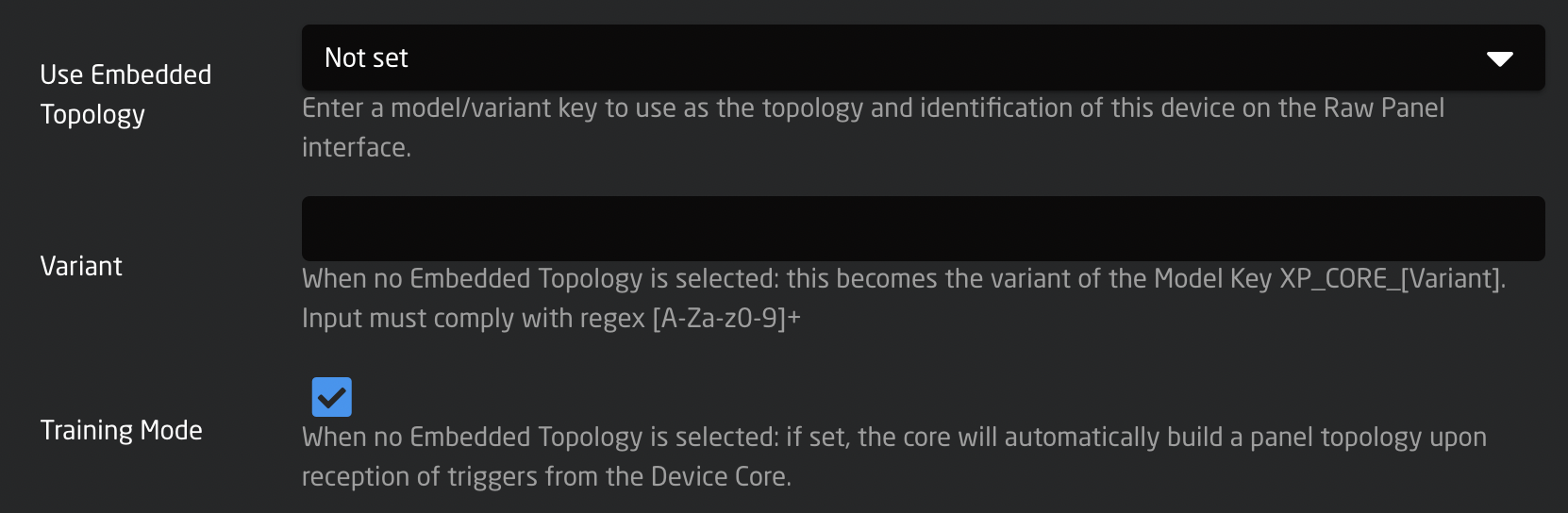](https://wiki.skaarhoj.com/uploads/images/gallery/2022-10/EfXimage.png)
Assuming we just set this up as Device 2 (make sure to pick another port, such as 9924) it would appear in Raw Panel Explorers network scan like this:
[](https://wiki.skaarhoj.com/uploads/images/gallery/2022-10/UbGimage.png)
When you connect you will see this:
[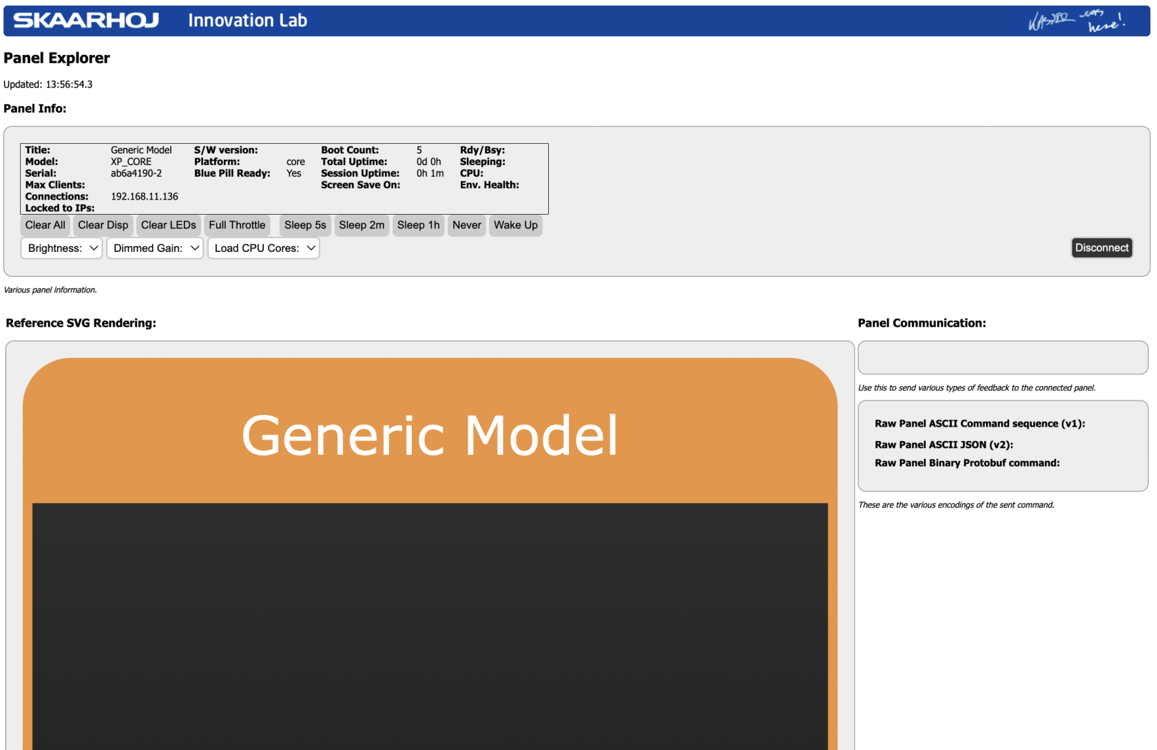](https://wiki.skaarhoj.com/uploads/images/gallery/2022-10/Ubpimage.png)
As you start pressing triggers that Reactor forwards to the panel, the Training mode will automatically build up an abstract topology like this:
[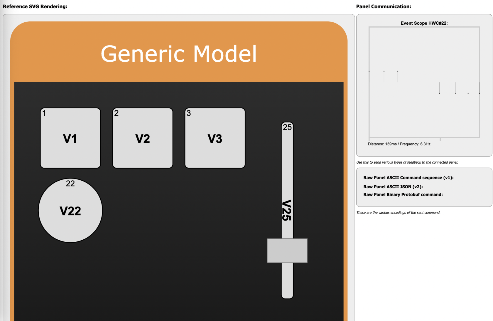](https://wiki.skaarhoj.com/uploads/images/gallery/2022-10/dqrimage.png)
In this case, three buttons were pressed (HWCids 1,2,3) , then a fader was moved (it had HWCid 25) and finally an encoder was turned left and right (HWCid 22). As long as the panel is in training mode it will add components to the panel like this.
Building an abstract panel like this can be useful in cases where the raw panel client rather wants to relate to "3 buttons, a fader and an encoder" type of panel and really doesn't care if in the other end it's mapped onto a Rack Fusion Live, PTZ Extreme or Air Fly Pro. That mapping could be done in any way inside Reactor regardless. When training is done, make sure to disable Training mode.
Building adhoc panels is an advanced option with some quirks related to it for now, so it's advised to discuss application with SKAARHOJ support team first. We really would like to know how you want to use this and help you succeed.
# Ross OGP - Model Dump
The Ross OGP core has the ability to capture all device parameter information and save it. This information can be used to help Skaarhoj add new models to the system.
This guide will show how to create a model dump.
#### 1. Connect to device
Connect to the device using a random model. Make sure the device states connected.
[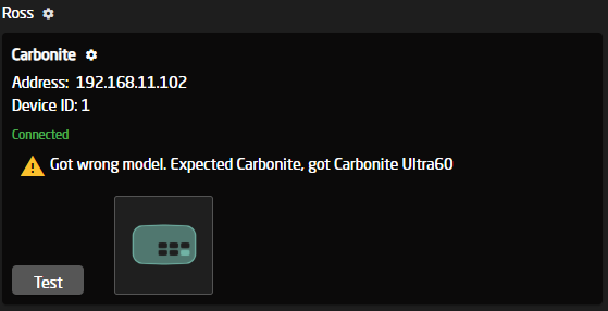](https://wiki.skaarhoj.com/uploads/images/gallery/2025-06/fnnimage.png)
#### 2. Set description prefix
Open the device configuration again and add 'learn\_mode' to the start of the description. Press save.
[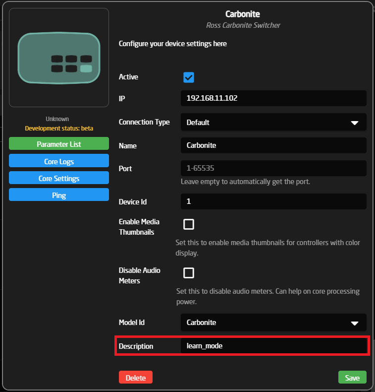](https://wiki.skaarhoj.com/uploads/images/gallery/2025-06/9Tjimage.png)
#### 3. Open logs
Open the device configuration again, and press the 'Core Logs' button.'
[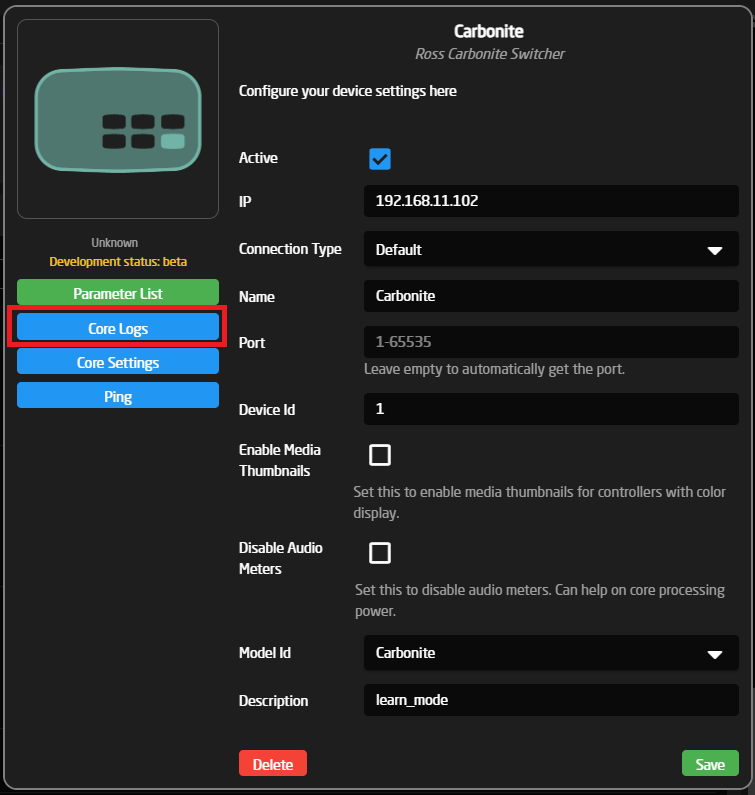](https://wiki.skaarhoj.com/uploads/images/gallery/2025-06/IQuimage.png)
#### 4. Download and send package
After about 30 seconds, you should see something like this in the core logs. If not, please reload the page.
The last log line here shows where to get the file from. For example, if your Skaarhoj panel is on '192.168.3.16', go to '192.168.3.16:8090/learn.zip'. This should begin a download of a zip file. Send this file to along with as much as possible information regarding the device you are connected too.
[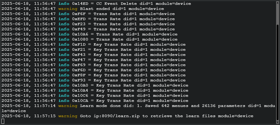](https://wiki.skaarhoj.com/uploads/images/gallery/2025-06/9Y3image.png)
# Setup Core-Email
This core will provide you with a quick way to send out emails, from the reactor ecosystem. using your own Gmail or resend.com setup. The core should also be compatible with other vendors, but we have only tested with these two.
#### Device Setup:
Please take a look at the two setup guides depending on what setup you need:
Generic-SMTP Setup (Gmail)
For Google (Gmail) you will need to first get an "app password" for your account, to do this please follow this guide:
[Create Gmail App Password](https://support.google.com/mail/?p=InvalidSecondFactor)
Once you have your App Password or if you are using another service, please check if you need some special setup there as well.
Add the device to reactor via the UI, the device should be the model called: "Generic SMTP Email"
[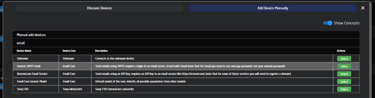](https://wiki.skaarhoj.com/uploads/images/gallery/2023-12/image.png)
As for the setup of the device you should fill in the email server address in the "host" field, as well as the port nr into "port" (marked in red below).
Then fill in your username, which is normally your email address, as well as the password for the same account, if you are using Gmail paste the app password from before into the same password field instead of your user password. (Marked in blue)
Last set up the email address that these emails will be sent from ("Sender Email"), this is normally the same as the username for this kind of server. and if you want to be able to test the core fill in the "Test Email" (Marked in green)
[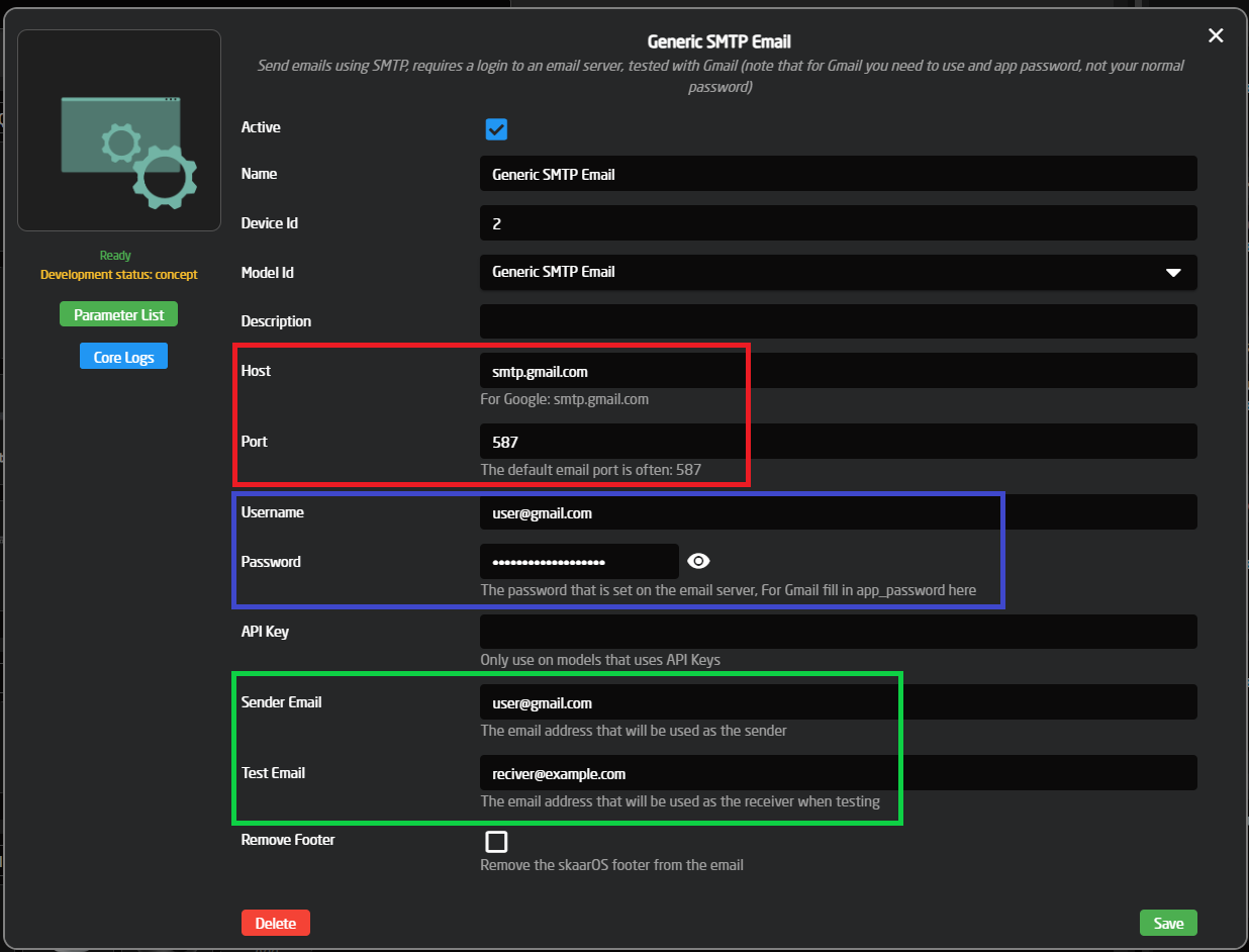](https://wiki.skaarhoj.com/uploads/images/gallery/2023-12/uv1image.png)
API Key is not needed for this device.
Click Save and you should now see your new device added to your device collection, and to test if it works, you can use the test button to send a Test mail to the "Test Email" specified above.
[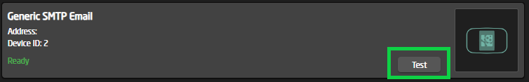](https://wiki.skaarhoj.com/uploads/images/gallery/2023-12/zcyimage.png)
Resend.com Setup
Before you can use the Resend.com device, you will need to set up an account and add a domain to the account
And then generate an API Key for use with this device, you can follow this guide for the full setup:
[Resend.com Verify Domain](https://resend.com/domains)
[Resend.com Create API Key](https://resend.com/api-keys)
Add the device to reactor via the UI, the device should be the model called: "Resend.com Email Service"
[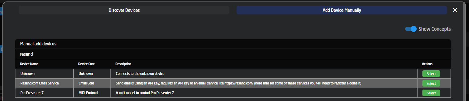](https://wiki.skaarhoj.com/uploads/images/gallery/2023-12/FuDimage.png)
For Resend.com we only need to fill in the API key in the "Green" field, and a valid email from the domain we set up on Resend.com into the "Sender Email", marked in "Red". if you wanna be able to test the device, please fill in the "Test Email" as well as that would be the email receiving the email when the test button is triggered
[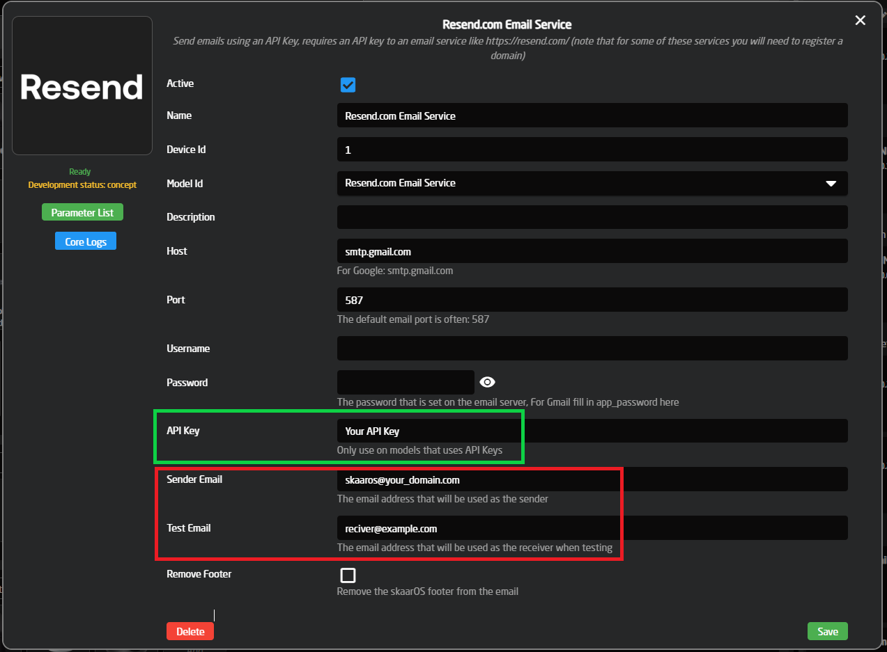](https://wiki.skaarhoj.com/uploads/images/gallery/2023-12/QAEimage.png)
Host, Port, Username and Password are not used for this device, so you can clear them or just leave them as they are.
Click Save and you should now see your new device added to your device collection, and to test if it works, you can use the test button to send a Test mail to the "Test Email" specified above.
[](https://wiki.skaarhoj.com/uploads/images/gallery/2023-12/ZTSimage.png)
#### How to send an email from a button press:
to be expanded
# Sony FX3
Connection and control of the Sony FX3 is possible via Skaarhoj panels with USB-A ports. This is because the Sony FX3 only supports the Sony Remote SDK using Serial USB and not through wifi or direct network connection.
**Physical Set Up**
Using a USB-C to USB-A cable, connect the Sony FX3 to a Skaarhoj panel with a USB-A port.
Please note, multiple cameras can be control by using a USB hub into the Blue Pill device.
Skaarhoj Panel
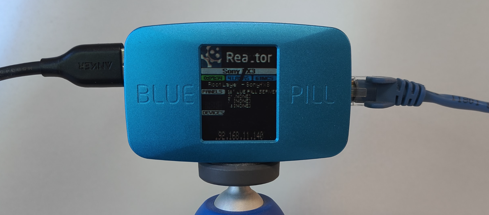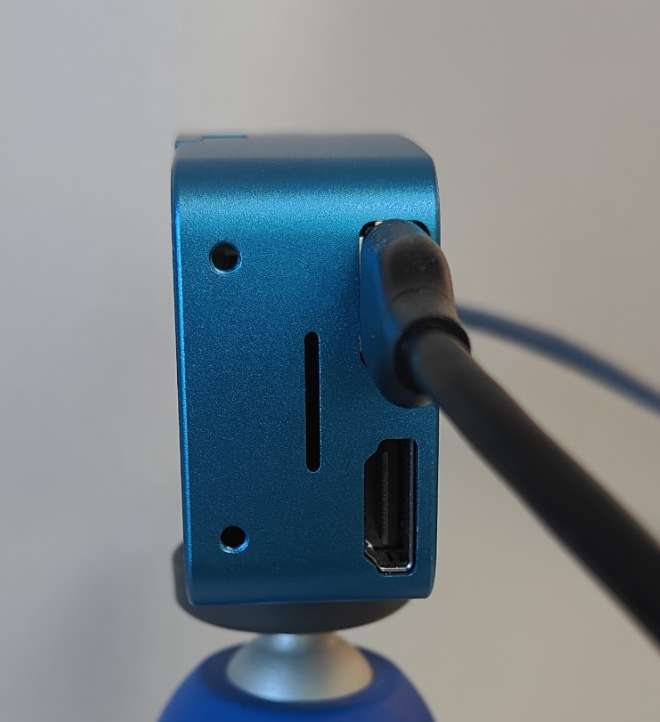
Sony FX3
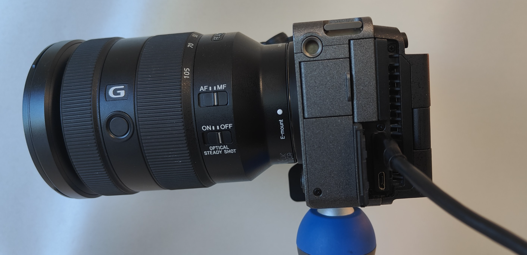
**Skaarhoj Set Up**
On the Setting Page, enable the USB-A port.
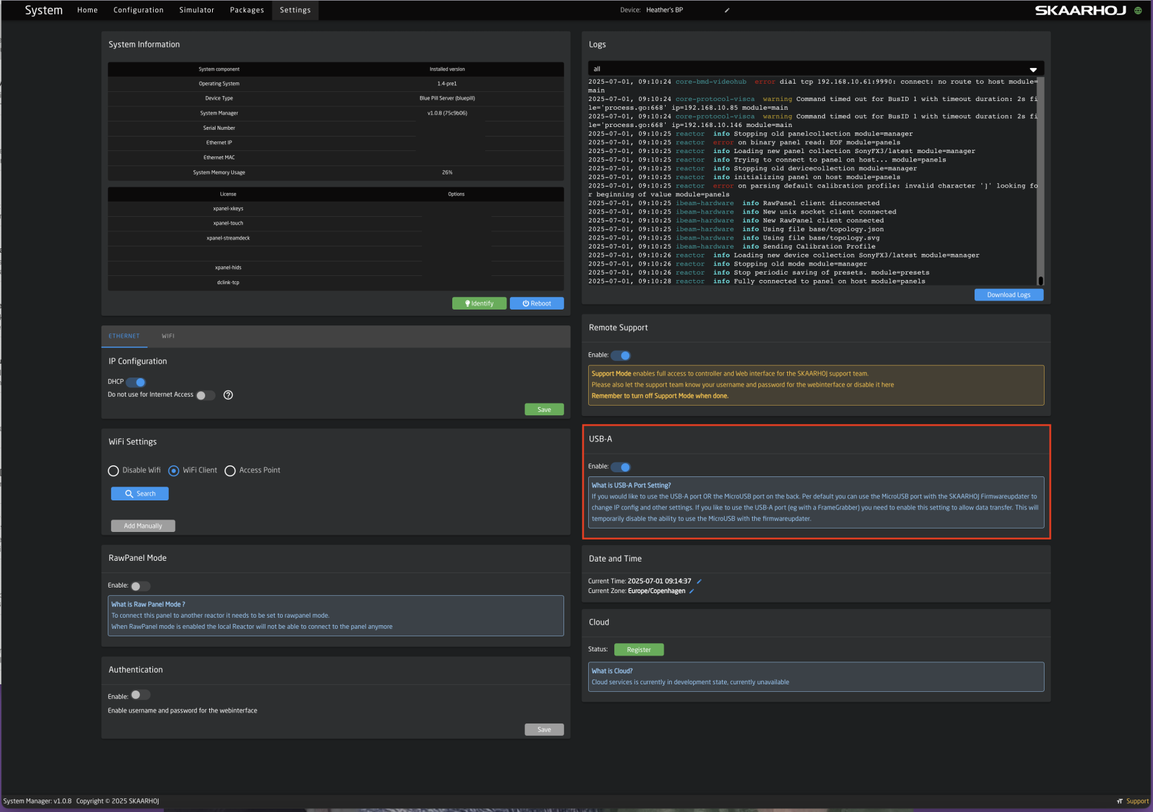
On the Home Page, add the Sony FX3.
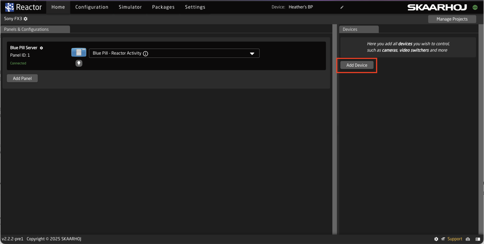
Please note, the Sony FX3 needs to be added manually and can not be auto discovered.
It may also be necessary to enable Show Concepts.
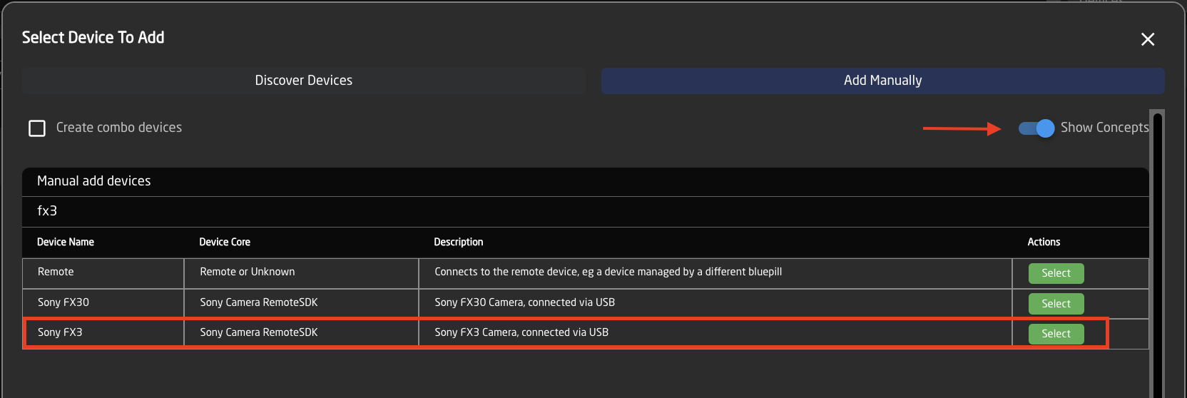
There should be no additional information needed in the device details, simply press save.
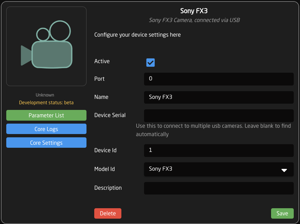
You should see confirmation of device connection on the home page.

If you do not see confirmation of connection please try rebooting your Skaarhoj panel and check the USB cable is properly connected.
**Control**
Once connection has been established, it is possible to control the Sony FX3 from any Skaarhoj panel connected through the same Blue Pill device.
If control is to be established from a Skaarhoj panel that is not set up in the same user interface, please see instructions for [Sharing Device Cores Across Different Blue Pill Devices](https://wiki.skaarhoj.com/books/blue-pill-reactor/page/sharing-device-cores-across-different-blue-pills).
# Sony FX6
You can connect to Sony FX6 camera via cabled Ethernet or Wifi. We **strongly** suggest to use cabled Ethernet.
This will work with multiple FX6 cameras - they just need to have unique IP addresses.
#### Wired LAN setup
You need to enable Wired LAN in the camera settings:
• Menu > Network >
\- Access Authentication > Input password > set new password
\- set Wired LAN = ON
\- set Remote Control = ON
Also, you must set a static IP address:
• Menu > Network > Wired LAN > Detail Settings >
\- DHCP = OFF
\- Enter static IP / Subnet / Gateway
[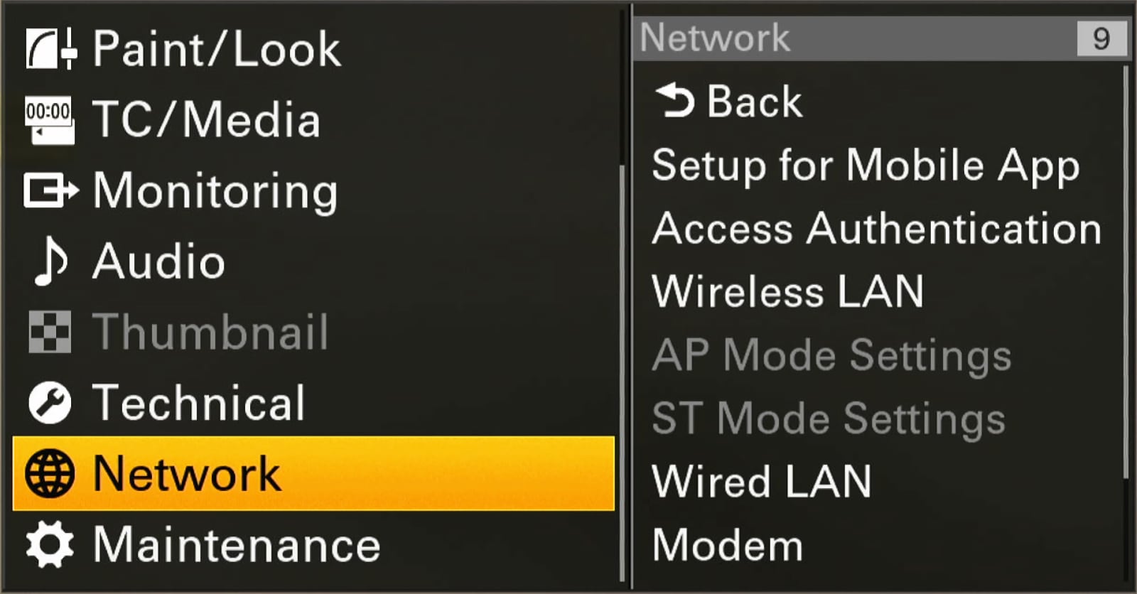](https://wiki.skaarhoj.com/uploads/images/gallery/2024-03/network-menu.jpg)
#### USB-C to Ethernet adaptor
To use cabled Ethernet, you need a "USB-C to Ethernet adaptor".
It is critical that you use an adaptor with compatible chip-set:
- Realtek RTL8153
- AX88179
Note: There are many other adaptors not working. They can even crash the FX6. This includes a chip-set with similar name; AX88179**A** - (has an A at the end) which does NOT work.
Here is an example of a working adaptor from a Danish webshop (availability of this product may expire):
[https://www.av-cables.dk/usb-3-1-til-rj45-netvaerksstik/delock-usb-c-3-1-gen1-ethernet-adapter-10-100-1000-mbps-s.html](https://www.av-cables.dk/usb-3-1-til-rj45-netvaerksstik/delock-usb-c-3-1-gen1-ethernet-adapter-10-100-1000-mbps-s.html)
Another product (this is NOT tested by us, but has correct chipset):
[https://www.proshop.dk/Netvaerksadapter-netkort-printserver-mv/AXAGON-Gigabit-Ethernet-USB-C-External-Network-Adapter/3414405](https://www.proshop.dk/Netvaerksadapter-netkort-printserver-mv/AXAGON-Gigabit-Ethernet-USB-C-External-Network-Adapter/3414405)
[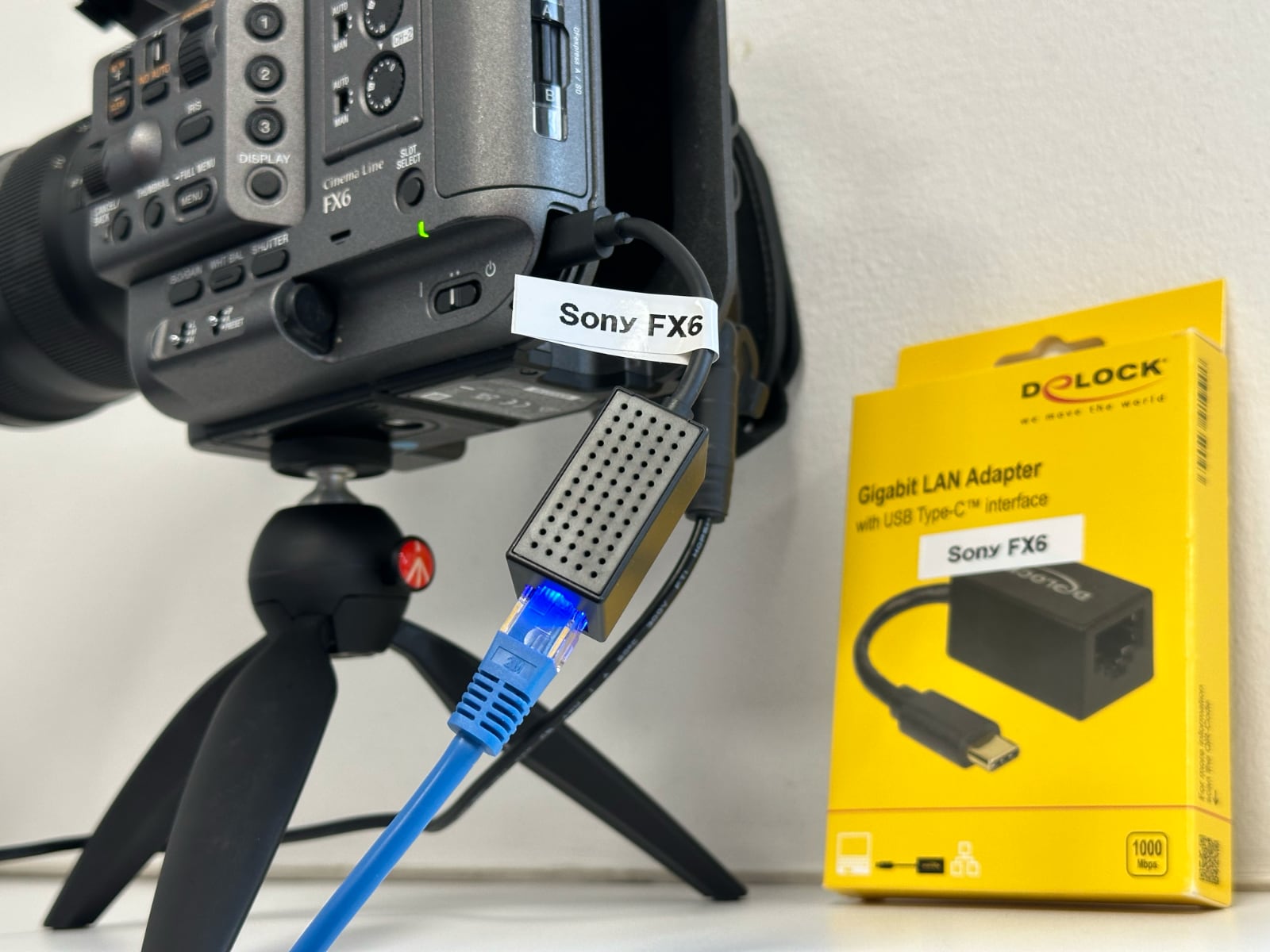](https://wiki.skaarhoj.com/uploads/images/gallery/2024-03/sonyfx6-usbadaptor.jpg)
# Sony ILME-FR7
In order to connect to the SONY ILME-FR7/ILME-FR7K cameras, make sure you have VISCA enabled on the camera. This can be done by setting this DIP-Switch on the unit:
[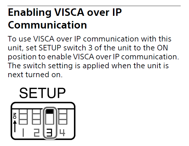](https://wiki.skaarhoj.com/uploads/images/gallery/2022-12/hJeimage.png)
---
**EXTERNAL TALLY**
To enable Tally control from a BluePill device please enable "External Tally" in the cameras Web-UI:
[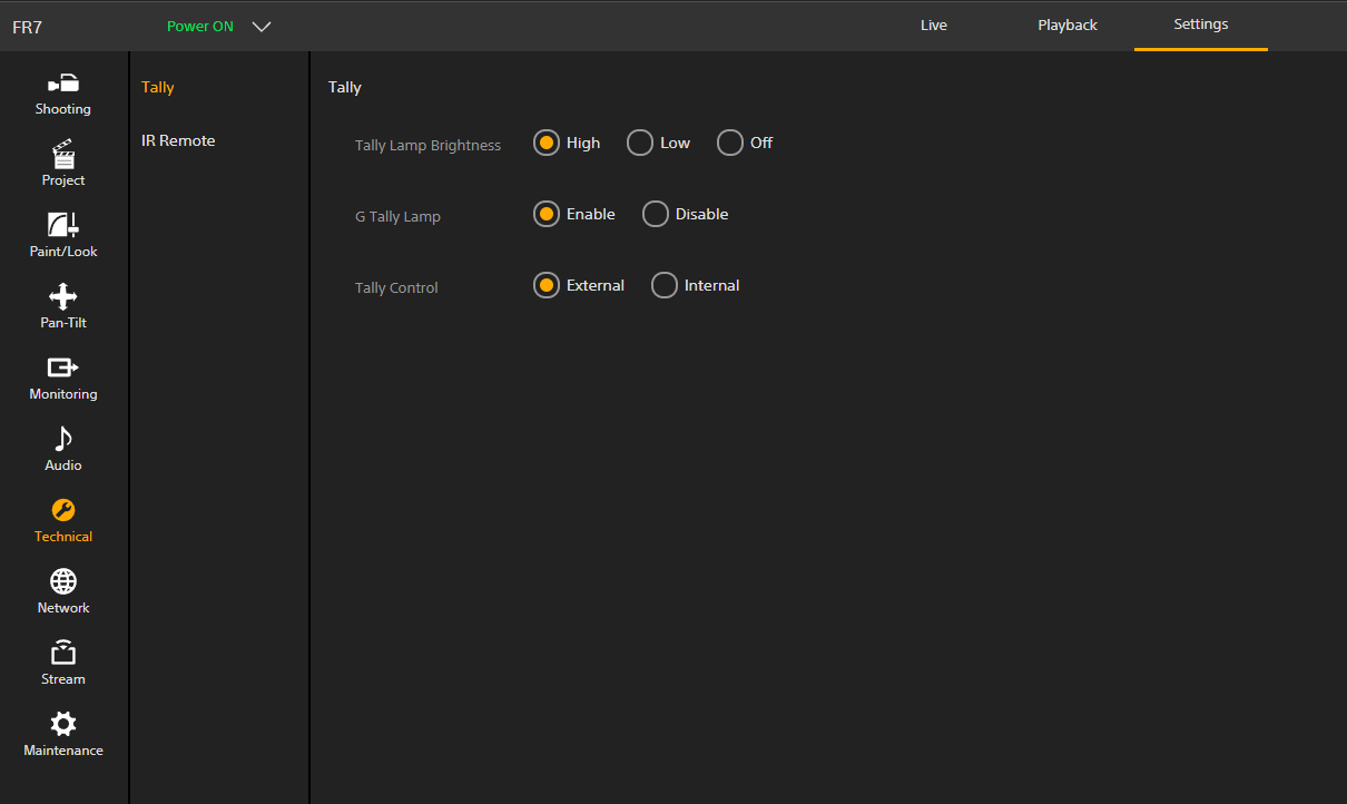](https://wiki.skaarhoj.com/uploads/images/gallery/2022-12/QAOimage.png)
---
**ADDING DEVICE TO REACTOR**
When adding this device to Reactor, it should look like this, and it should also come up as an auto discovered device if you have NDI-HX enabled on the unit, even if you don't have the license for it:
[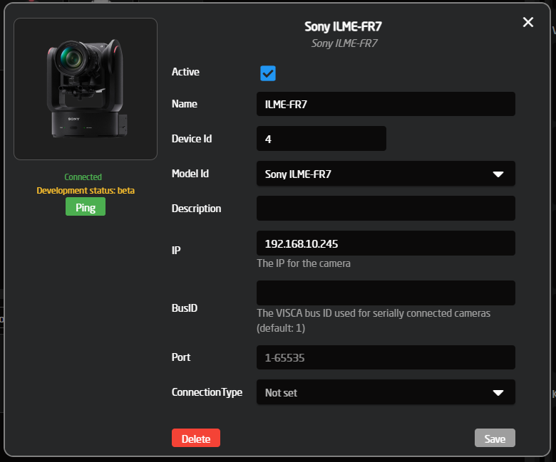](https://wiki.skaarhoj.com/uploads/images/gallery/2022-12/QgQimage.png)
---
**SPEED CONTROL**
The joystick speed is not only controlled by the 'JoystickSens' variable. This camera has 3 parameters to control the speed of the PTZ movement.
For maximum speed, please use:
- "CAM\_PTSPEEDSTEP" sets the range > set this to '9'
- "CAM\_PTSLOWMODE" > needs to be 'off'
- "CAM\_PTRAMPCURVE" is the accel speed > set this to 'Extend'
[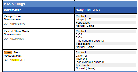](https://wiki.skaarhoj.com/uploads/images/gallery/2022-12/commands.png)
Device core command list:
[https://cloud.skaarhoj.com/coremanual/core-protocol-visca/pre/2811](https://cloud.skaarhoj.com/coremanual/core-protocol-visca/pre/2811)
---
**NO CONNECTION**
If you have the experience that it just wont connect at all, after having been working earlier, please try and restart the camera, there might be a client limit on the device
To be expanded upon.
# TCP Device Core / UDP Device Core
The TCP Device Core for Blue Pill, *core-protocol-tcp*, allows users to send and to some extend receive and process information of TCP to both ASCII and binary servers. Effectively, this can help to bridge communication with devices where a dedicated device core is not available.
The UDP Device Core for Blue Pill, *core-protocol-udp*, enables the exact same functionality as for TCP, just over a UDP connection.
This page describes how both device cores work, but using core-protocol-tcp as the example. The device cores have both a very basic mode and some more complex features that can come in handy in some cases. It has been designed to align with the corresponding TCP Client device core on the UniSketch platform.
### Commands
The commands you can specify and send are ASCII by default and exactly what you see in the string will be sent as ASCII, unless:
- **\\n** and **\\r** will send a newline or carriage return (bytes 10 and 13)
- **\\xHH** will send a byte with the value HH (in hex): so \\xFF will send a byte with value “255”
- **\\p1,** **\\p2** or **\\p3** (alternatively **\\d1, \\d2, \\d3, \\h1, \\h2, \\h3, \\i1, \\i2, \\i3, \\f1/\[scale\], \\f2/\[scale\], \\f3/\[scale\]**) will insert a parameter value as defined by the meta value p1, p2 and p3 in the device core parameters Toggle, On Trigger and Off Trigger.
The difference of using \\p, \\d, \\i, \\f and \\h is whether the meta value is inserted as the byte value (\\p), inserted as a byte decimal number like “255” or “37” or “3” (\\d - there is no leading zeros), as a signed 32 bit integer (\\i), as a floating point number (\\fx/\[scale\]) or in hexadecimal like FF or D0 or 00 (\\h - in this case it’s always two characters and uppercase).
##### Floating point
Inserting a floating point number with \\f is based on the parameter p1-p3 being an integer which gets divided by the \[scale\] number. For example, if you insert \\f2/10 then if meta value parameter p2 is a variable with the value 55, it will get formatted as "5.5" in the message.
#### **Example**
Say you want to send a command to fire DMEMs on GVG100, in that case you want to send the text string “03 01 DB 00” to fire DMEM 01, send “03 01 DB 01” to fire DMEM 02 etc.
So setting up a command like “03 01 DB \\h1” and then using the “p1” meta value through a constant in Reactor would allow you to distribute the same behavior across multiple hardware components on a panel but vary the Dmem value easily.
### Testing and tools
An advice is to use the "[ipserver](https://github.com/SKAARHOJ/raw-panel-utils/tree/main/IPtools/binaries)" binary tool provided by SKAARHOJ to set up a server to help testing the functionality until you are confident that everything works as expected and would function with the final target device.
### Basic Configuration
The device core has some configuration fields:
[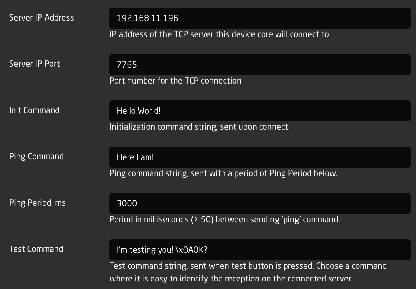](https://wiki.skaarhoj.com/uploads/images/gallery/2022-10/CxAimage.png)
- IP address and port for the server should be straight forward.
- The Init Command is a command string that will be sent to the server one time upon a new connection.
- The Ping Command will be send periodically. The period between its being sent will be 3000 ms in this case.
- The Test Command is send when the Test trigger is activated (that's typically available as a button in Reactor)
### Cowboy Style
The most straight forward way to use the device core would be to send one-shot triggers *cowboystyle*. This requires the minimum of configuration but provides the least amount of long term convenience. This is probably a good place to get started.
[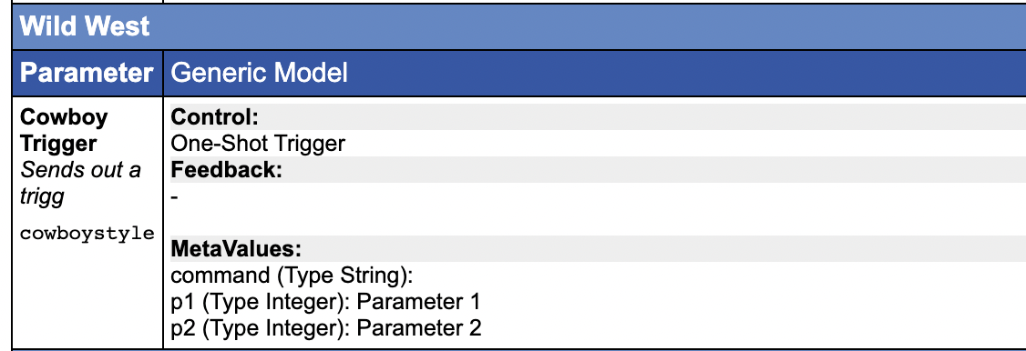](https://wiki.skaarhoj.com/uploads/images/gallery/2022-10/S4Aimage.png)
### Command Configuration
The device core allows you to configure a number of fixed commands. The advantage is that you can bundle an A and B command into a single action for toggles etc. Also, this is the way you can use meta values with the \\p1,\\p2, ... placeholders etc. Finally, it's actually possible to decode some level of status back from the returned content of the device via a regular expressing.
[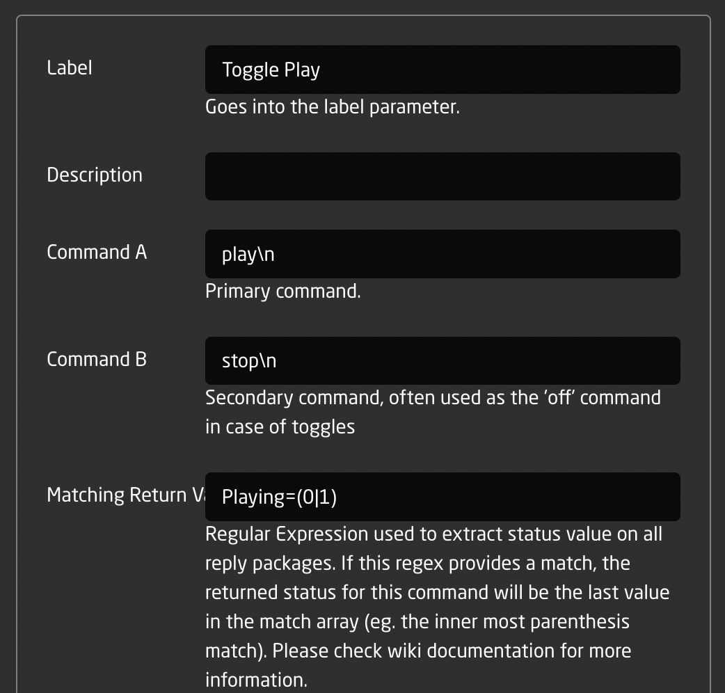](https://wiki.skaarhoj.com/uploads/images/gallery/2022-10/p8Himage.png)
- The Label field will be set as a fixed value in the device core so you can import it as a label in Reactor
- The Command A and B are available to easily create toggle functionality
- The Matching Return Value field contains a regular expression. You can study the format of regular expressions elsewhere, but they are basically very powerful and advanced string matching patterns. Whenever the device core receives feedback from the server it will run all regular expressions set up over each line and whenever there is a match, it will take the value in parenthesis and store as the status value in the corresponding Status parameter in the device core.
The commands configured here will be available through these parameters in the device core:
[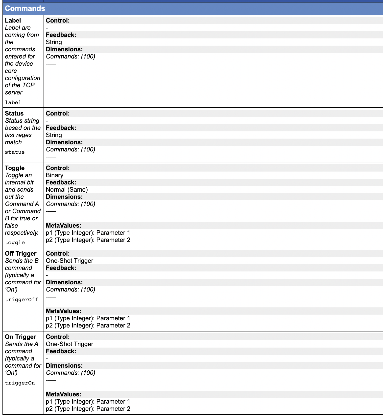](https://wiki.skaarhoj.com/uploads/images/gallery/2022-10/PVSimage.png)
- Toggle, Off Trigger and On Trigger allows various ways of using the command, either by a one-shot type action or by a standard toggle action that keeps internal state in the controller (without any confirmed feedback).
- Label is the text label from configuration. You may want to use this to set a nice title in the displays
- Status is the match value from the last time the regular expression matched the return content. Used carefully, this can provide some feedback from a remote system.
### Examples
#### Forwarding the position of a fader, 0-1000
Forwarding the position value of a fader requires us to use the "\\i" placeholder to insert a dynamic value. The code below demonstrates a behavior called "VolumeFader" that is assumed to control volume on a given channel on a device by sending text strings like "CHx\_Vol\_n", where x is the channel number and n is the volume. In this case, we assume the device will access the value range of n to go from 0 to 1000 so that it's 1:1 compatible with a Raw Panel fader position value.
```json
"VolumeFader": {
"ConstantDefinitions": {
"Channel": {
"Description": "Channel",
"Type": "Integer"
},
"DeviceId": {
"Description": "Device Id",
"Type": "Integer"
}
},
"EventHandlers": {
"trigger": {
"AcceptTrigger": "Binary",
"EventPreProc": {
"A2B": {
"InputMapping": {
"Default": {
"Threshold": 2,
"RepeatThresholds": true,
"OutputTriggerRising": "ActDown",
"OutputTriggerFalling": "ActDown"
}
}
}
},
"IOReference": {
"Raw": "DC:protocol-tcp/{Behavior:Const:DeviceId}/cowboystyle/",
"MetaValues": {
"command": "CH\\d1_Vol_\\i2",
"p1": "Behavior:Const:Channel",
"p2": "Behavior:LastEvent/Analog:Value"
}
}
}
}
}
```
Description:
- Lines 2-11 describes a constant definition. This will make the Configuration UI draw up two fields that makes it easy to pick the device ID and Channel number for this behavior. This makes the behavior suitable as a Master Behavior that can be easily reused. It would look like this:
[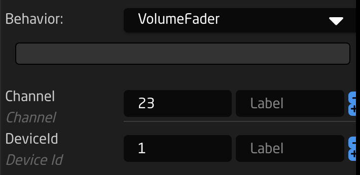](https://wiki.skaarhoj.com/uploads/images/gallery/2022-12/TN1image.png)
- Lines 14-26: The event handler is set up to trigger on a binary input and the reason why this works for a fader is because the Event Pre Processor in lines 15-26 will convert any change to fader position into a binary trigger.
- Lines 27-24 is the IO reference. When the fader is moved, leading to the generation of a binary trigger, the IO reference is triggered too. The value of the fader is loaded into parameter 2 and the value (constant) of the channel is loaded as parameter 1. Parameter 1 is inserted by \\\\d1 into the command while the fader value is inserted as \\\\i2. (The double backslash is the same as a single backslash in JSON)
#### Forwarding the position of a fader, arbitrary interval
Forwarding the position value of a fader in a different range is more trouble, but can be done. We will use a behavior variable for that. This is a variable only available in the scope of the behavior definition.
```json
"VolumeFader": {
"ParentID": "SKAARHOJ:FaderMotorized",
"Variables": {
"FaderValue": {
"Name": "Volume",
"MinMaxCenterValue": [
0,
100
],
"DefaultToFirst": true
}
},
"ConstantDefinitions": {
"Channel": {
"Description": "Channel",
"Type": "Integer"
},
"DeviceId": {
"Description": "Device Id",
"Type": "Integer"
}
},
"IOReference": {
"Raw": "Var:FaderValue"
},
"EventHandlers": {
"forward": {
"AcceptTrigger": "Binary",
"EventPreProc": {
"A2B": {
"InputMapping": {
"Default": {
"Threshold": 2,
"RepeatThresholds": true,
"OutputTriggerRising": "ActDown",
"OutputTriggerFalling": "ActDown"
}
}
}
},
"IOReference": {
"Raw": "DC:protocol-tcp/{Behavior:Const:DeviceId}/cowboystyle/",
"MetaValues": {
"command": "CH\\d1_Vol_\\d2",
"p1": "Behavior:Const:Channel",
"p2": "Var:FaderValue"
}
}
}
}
},
```
Description:
- Line 2 defines that we will inherit the master behavior "SKAARHOJ:FaderMotorized". By doing so we "just need" to add an IO reference (parameter) to be changed by the fader and everything else will just work. But, we will extend it quite a bit with some tricks here.
- Lines 3-12 define a behavior variable "FaderValue" which will be used to hold the value we forward. The range is 0-100. This variable can only be used and seen from within this behavior.
- Lines 13-22 has the constants definitions as in the previous example
- Line 24 is the IO reference (parameter) set to the local behavior variable, "FaderValue". So far, what we have is a fader that will simply change the value of the variable "FaderValue" when you move it. Not useful yet.
- Line 27 defines a new event handler which is the code that will take the value of "FaderValue" and forward when the fader is moved. It accepts a binary trigger and has the analog values of the fader generating a binary trigger event when moved (just like in the previous example).
- Lines 44-46 defines the meta values for using the cowboystyle parameter for the TCP device core. Again, the parameters p1 and p2 are loaded with dynamic values from IO references, the Channel constant and the FaderValue respectively. Those are then inserted as decimal bytes in the command string by the placeholders \\\\d1 and \\\\d2
#### Sending TCP commands with an encoder
This examples shows how to program an encoder to send a different command whether you turn it clockwise or counterclockwise. It's build over the same idea as in the previous examples where the behavior is design for use as a Master Behavior, using a constant definition for the channel and Device ID.
```json
"VolumeUpDown": {
"Description": "QSYS Volume Up/Down for Encoders/4Ways",
"ConstantDefinitions": {
"Channel": {
"Description": "Channel",
"Type": "Integer"
},
"DeviceId": {
"Description": "Device Id",
"Type": "Integer"
}
},
"IOReference": {},
"EventHandlers": {
"down": {
"AcceptTrigger": "Binary",
"EventPreProc": {
"P2B": {
"InputPolarity": {
"Default": {},
"Negative": {
"OutputTrigger": "ActDown",
"OutputEdge": "Left"
}
},
"SpeedmodeConfig": {}
}
},
"BinaryEdgeFilter": "Left",
"BinarySetValues": {},
"IOReference": {
"Raw": "DC:protocol-tcp/{Behavior:Const:DeviceId}/cowboystyle/",
"MetaValues": {
"command": "CH\\d1_Down",
"p1": "Behavior:Const:Channel"
}
}
},
"up": {
"AcceptTrigger": "Binary",
"EventPreProc": {
"P2B": {
"InputPolarity": {
"Default": {},
"Positive": {
"OutputTrigger": "ActDown",
"OutputEdge": "Right"
}
},
"SpeedmodeConfig": {}
}
},
"BinaryEdgeFilter": "Right",
"BinarySetValues": {},
"IOReference": {
"Raw": "DC:protocol-tcp/{Behavior:Const:DeviceId}/cowboystyle/",
"MetaValues": {
"command": "CH\\d1_Up",
"p1": "Behavior:Const:Channel"
}
}
}
},
"FeedbackDefault": {
"DisplayText": {
"Title": "Ch. {Behavior:Const:Channel} Volume",
"Textline1": "Up/Down"
},
"Intensity": "Dimmed"
},
"FeedbackConditional": {
"10": {
"ActiveIf": "Behavior:Events/trigger:TimeToNow \u003c 300",
"Intensity": "On"
}
}
}
```
Description:
- The event handlers "down" and "up" in lines 15 and line 39 are almost identical and works like this: They activate on a binary trigger, but requires a Left or Right edge press of a four-way button. When encoders sends triggers into this behavior it gets captured and converted by the "P2B" event pre processor that converts a positive encoder pulse into a "right edge" binary trigger. Vice verse for a negative encoder pulse.
- The IO reference in line 55-61 and 31-37 is similar to the ones for faders, but doesn't hold any dynamic value other than the Channel ID from the constants
- In addition, since encoders often has displays, the Feedback Default and Feedback Conditional is set up to show the channel name and blink when activated.
# TCP Server Device Core
The TCP Server Device Core for Blue Pill, known as *core-skaarhoj-tcpserver*, enables users to connect one or multiple TCP clients to the device core, and read/write values to numerous internally stored data types. It's also an implementation of the data register section of the [TCP Server device core for UniSketch](https://github.com/SKAARHOJ/Support/blob/master/Manuals/DC_SKAARHOJ_TCPServer.pdf), mainly for legacy purposes. The key attraction for Blue Pill users is likely the significantly improved capacities:
- Strings: It supports the read/write operations for 200 strings, which also include titles for each.
- String Matrix: Users can read/write into a 20x100 string matrix.
- Integers: This system allows reading and writing of 200 32-bit signed integers, along with titles for each. Every integer can be set with distinct permitted value ranges, such as "-10 to 20".
- Booleans: It supports read/write operations for 200 boolean values, including titles for each.
- Option Lists: It allows the read/write of 200 option list values, with titles for each. Each option list can be set with an individual number of options, for example, "On" and "Off" or "Red", "Green", "Blue", "White", etc.
- Timers: It enables reading and writing of 200 boolean values, which automatically revert to false after a specific time period.
- Images: It lets users write 100 JPEG images and 100 PNG images into the device core (primarily intended for small images used for display graphics).
- From UniSketch: The device core implements Mem A-L, Flags 0-63, as well as Shift and State registers, mostly for legacy reasons.
The device core is generally multi-directional. Most values are set to read/write, and alterations from any client - whether the connected TCP clients or the device core clients - are propagated to other connected clients, ensuring synchronization at all times.
#### Use cases
The Device Core is an essential tool for ad hoc interactions with Reactor, which is the panel management application found on the majority of SKAARHOJ products. This utility is particularly beneficial for addressing custom integration needs. Below are a few examples:
- Create ad hoc Device Core parameters using integers and option lists. Leverage value ranges and custom options to allow Reactor to control custom applications through TCP.
- Utilize Reactor's Virtual Triggers to initiate actions on broadcast devices based on strings, integers, booleans, and option list values that are altered via TCP.
- Use a timer to either send a cut trigger or initiate recording on a device for a specific duration.
- Regulate a device's volume using an integer within a predetermined range.
- Select sources using an integer.
- Enable or disable functions using a boolean or option list.
- Create dynamic labels and icons
### Device Core Setup
In Reactor you would add the device core to the device list. The setup page looks like this:
[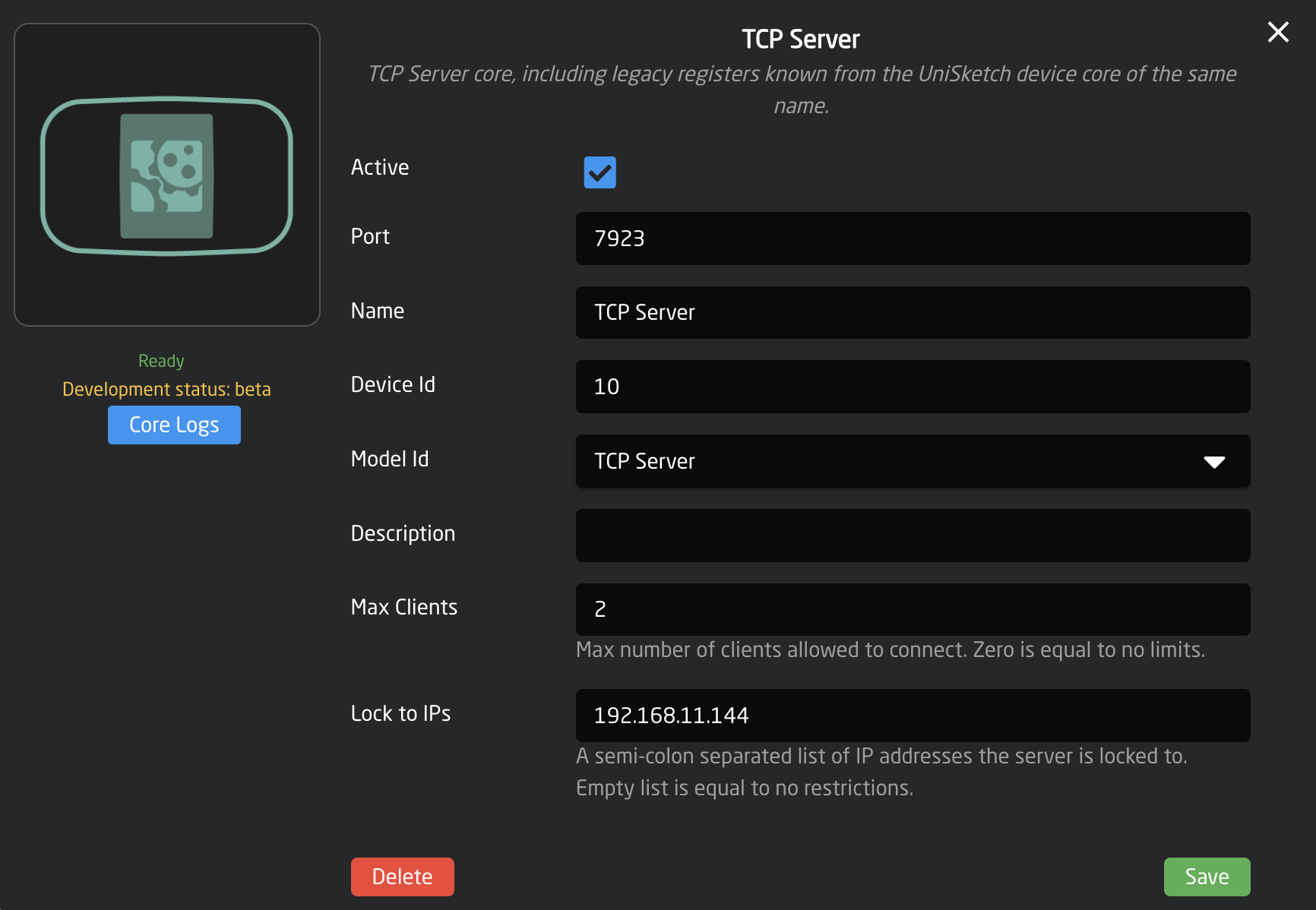](https://wiki.skaarhoj.com/uploads/images/gallery/2023-06/image.png)
- Port is the TCP port where the TCP server is created. If you create multiple servers, make sure these ports are different and not used by anything else. Please check the logs of core-skaarhoj-tcpserver under the Packages tab if you experience problems: there will be information about any issues in the logs.
- The Device ID is usually "1" and is used to reference the parameters inside the core.
- Max Clients is the maximum number of clients that can connect at the same time. A light weight security measure.
- Lock to IPs are specific IP addresses which are the only ones allowed to connect. A light weight security measure.
### Connect as a TCP Client
Using Putty, telnet or nc depending on your platform, you connect to the TCP server by using the IP address of the Blue Pill device hosting the device core and the port number. Here is an example. Connection is silent, there will be no introduction message sent to the connecting client, but typing in "help" and ending with newline (\\n or char 10) will show available commands:
[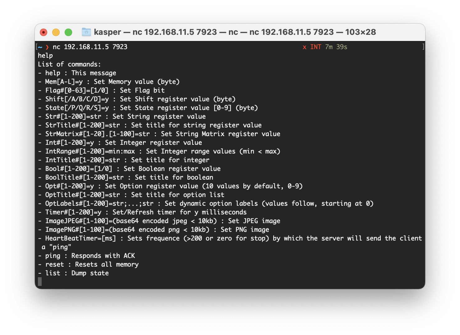](https://wiki.skaarhoj.com/uploads/images/gallery/2023-06/Hz5image.png)
If you are using Putty on Windows, make sure to set it up correctly to send newlines for line endings:
[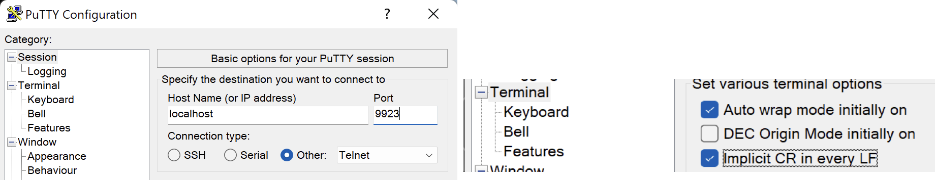](https://wiki.skaarhoj.com/uploads/images/gallery/2023-06/nz6image.png)
Try the different commands to get the feel for it.
### Example in Reactor
Here is an example of how Reactor can interface with an integer from the device core:
Click a hardware component in Configuration tab and assign a new behavior with an IO reference pointing to the Integer Value parameter of the TCP Server. Select integer #2 for example:
[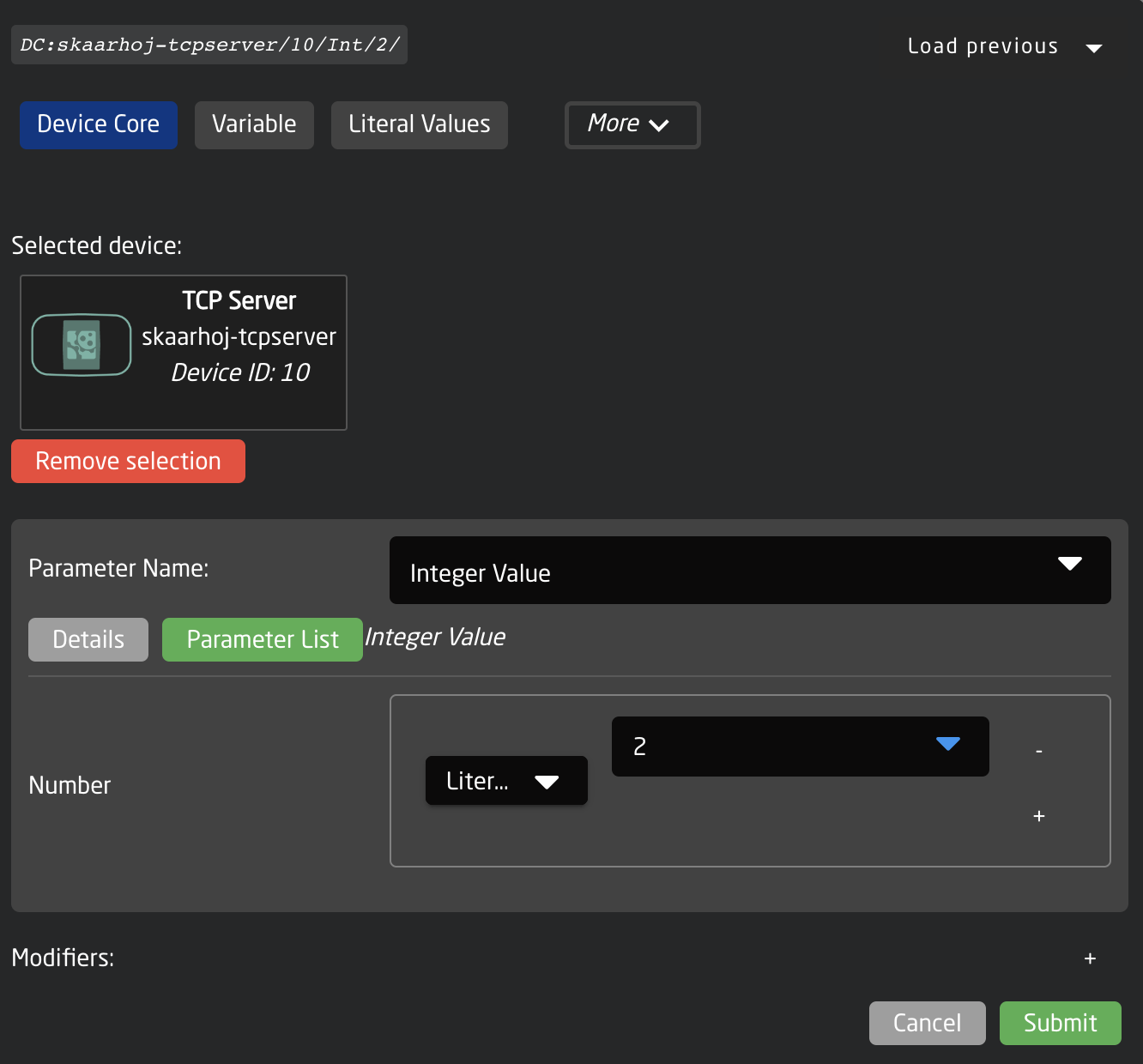](https://wiki.skaarhoj.com/uploads/images/gallery/2023-06/FZCimage.png)
You will see it in the display of the component, but it has no value:
[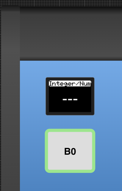](https://wiki.skaarhoj.com/uploads/images/gallery/2023-06/7uwimage.png)
Probably the "Change by Step" master behavior was assigned to the button as you selected the parameter, so if you press the button it should assume a value:
[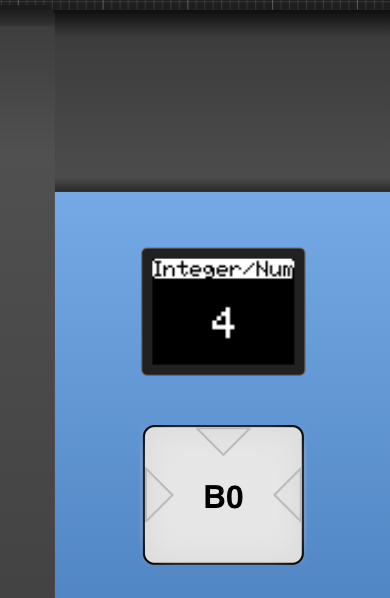](https://wiki.skaarhoj.com/uploads/images/gallery/2023-06/9Enimage.png)
Simultaneously, you should see values reported in the connected TCP Client window:
[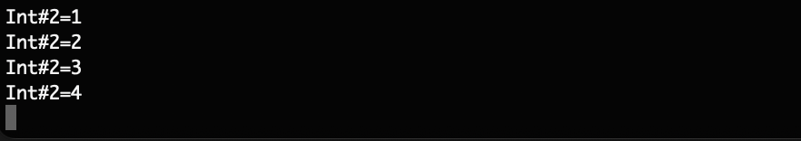](https://wiki.skaarhoj.com/uploads/images/gallery/2023-06/fVmimage.png)
In the TCP Client you can try to type in "Int#2=111" and you should see the value reported back in all connected TCP Clients as well as update in Reactor:
[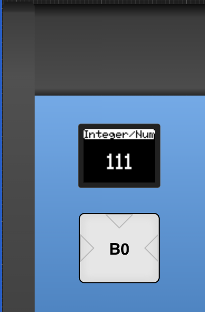](https://wiki.skaarhoj.com/uploads/images/gallery/2023-06/uAeimage.png)
The same can be done with all the other registers.
# Tilta Nucleus M
**The Tilta Nucleus Core supports control of Tilta Nucleus-M motors via a wired connection.**
It operates through a USB-to-UART (TTL) converter. We have tested it using this converter in 3.3V mode:
[https://www.waveshare.com/usb-to-ttl-d.htm](https://www.waveshare.com/usb-to-ttl-d.htm)
Other converters may work, but we cannot guarantee their compatibility. **Please ensure you use a 3.3V serial connection only.**
A custom cable is required to connect to the 7-pin LEMO connectors on the camera. This cable can be designed to provide both power and control, or control only.
[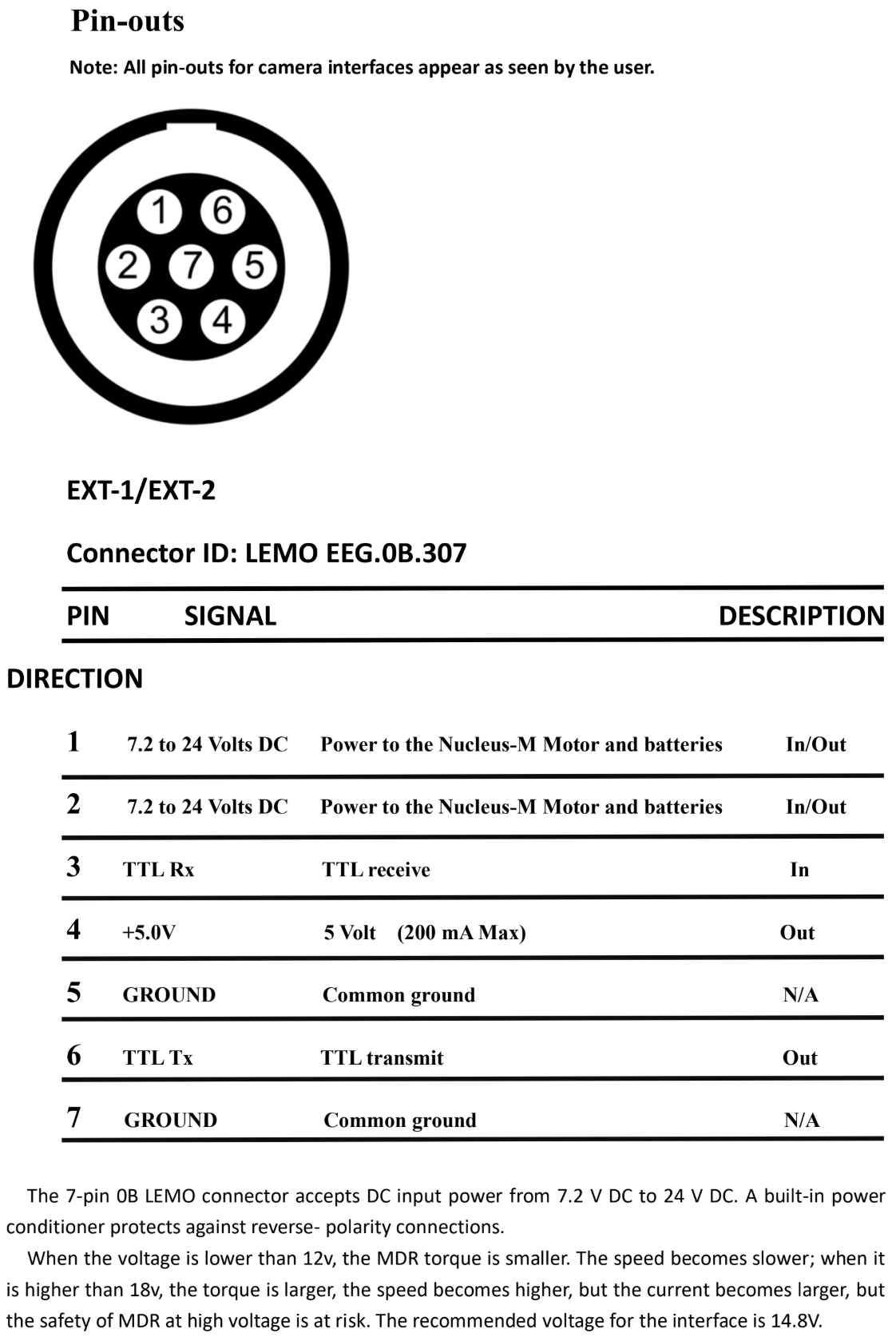](https://wiki.skaarhoj.com/uploads/images/gallery/2025-06/OJcimage.png)
# TSL
If you have a PTZ controller you can use TSL as the Routing trigger. That could be beneficial if you want your Camera selector to also route a source external in equipment using TSL, like Tallyman.
1. Add Cameras to your Controller
[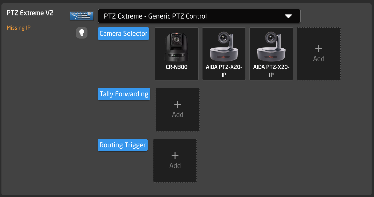](https://wiki.skaarhoj.com/uploads/images/gallery/2022-11/QhYimage.png)
2. Press Camera Selector
[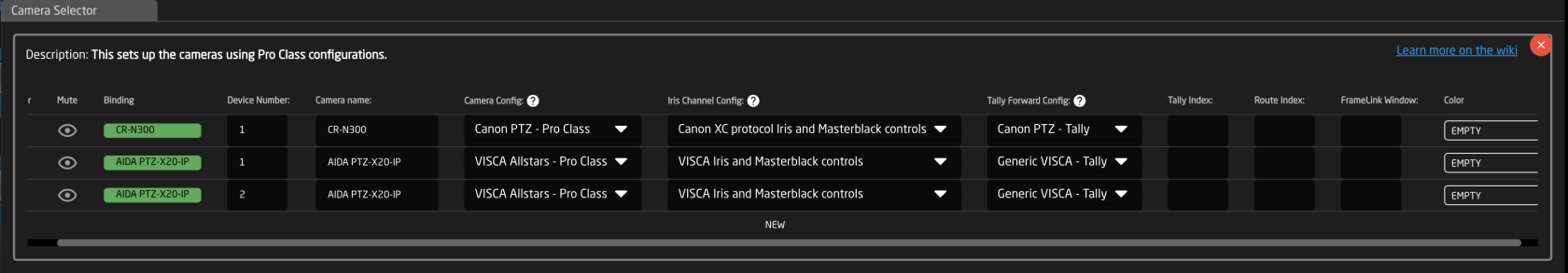](https://wiki.skaarhoj.com/uploads/images/gallery/2022-11/ZgOimage.png)
1. Fill in Route Index what TSL Address should be used for the specific source
3. Press Routing Trigger
1. Add new
2. Bind to your TSL Device
[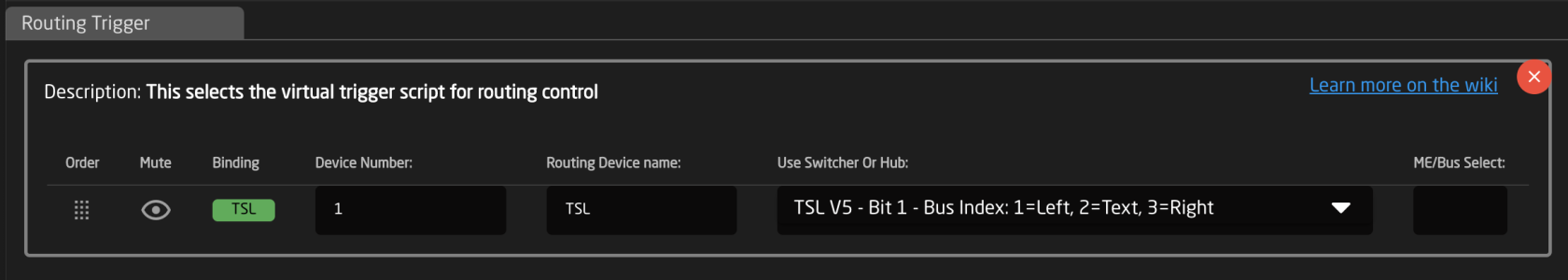](https://wiki.skaarhoj.com/uploads/images/gallery/2022-11/k4Oimage.png)
3. Select TSL Config in the Switcher or Hub section
[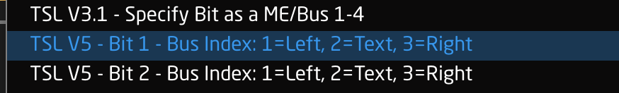](https://wiki.skaarhoj.com/uploads/images/gallery/2022-11/7gyimage.png)
4. Specify what Tally bit (v3.1) or Position (v5.0) you want to use
*Note: that the ME/Bus field is only used by TSL v3.1 and can be left blank when using TSl v5*
# Vimeo Livestream Studio
Before connecting the core to Livestream Studio first time you need to check in the Hardware Control if Third-party controllers are enabled.
After you can start connecting your core to Livestream Studio. Your connection appears in pending connection -> You need to allow this connection and only after that core will able to connect to Livestream Studio.
So, As a result, you should have your BP address in the allowed connection.
[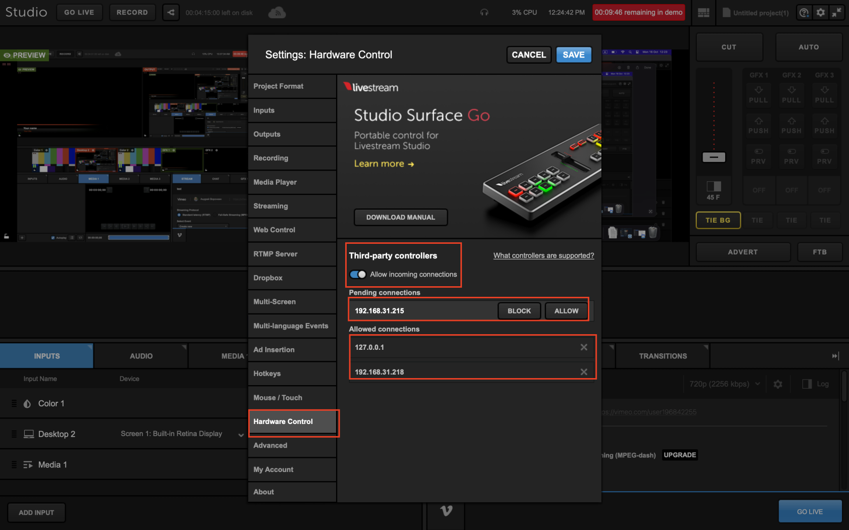](https://wiki.skaarhoj.com/uploads/images/gallery/2023-10/screenshot-2023-10-16-at-12-24-43.png)
#### Auto-Discovery Of Livestream Studio
On the Blue Pill platform, we support auto-discovering devices. Livestream Studio 6 does currently not have a native way for us to do this by default, but if you go into settings and add an NDI output, then we can use that for discovery. For that to work, you will need to include at least one of 3 words in one or more outputs:
- vimeo
- livestream
- studio
Once set up, it will look something like the below, and it should now show up in the device discovery list:
[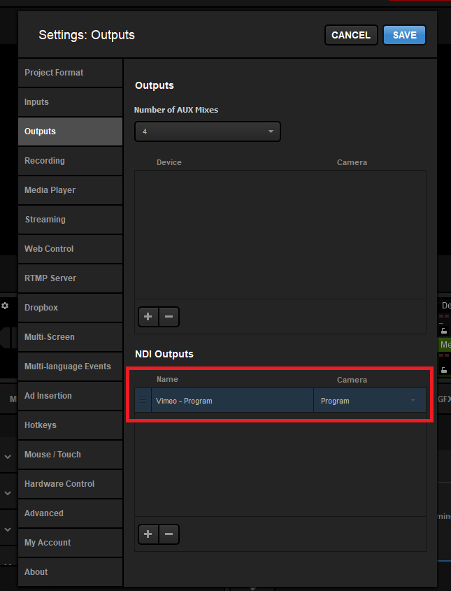](https://wiki.skaarhoj.com/uploads/images/gallery/2024-03/kRaimage.png)
# vMix v25 +
### Connecting To vMix v25For your Blue Pills to control vMix v25 or v226, please check the setting marked in RED as that needs to be turned on, as shown below.The settings marked in green are not required but recommended for the security of your vMix setup and to limit others from taking control from outside the LAN network.
**Note:** vMix v24 is not affected by this and will work out of the box. No changes are needed inside vMix.
[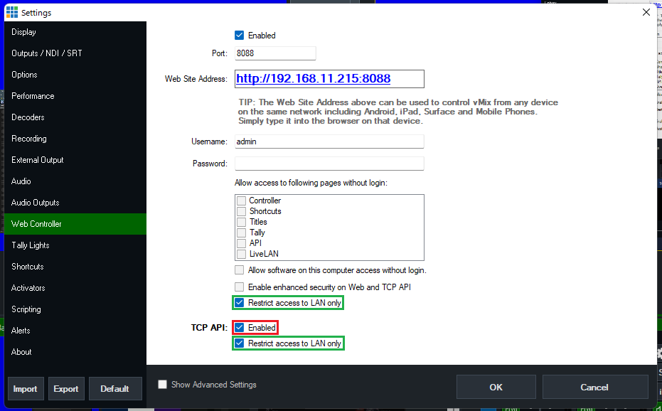](https://wiki.skaarhoj.com/uploads/images/gallery/2022-05/vmix-v25-settings.png)
### Add device inside ReactorInside reactor you can add any vMix device like normal, and the only thing you need to add is the IP of your vMix machine. We do have the option to change the port number used. Please **do not touch** it if you don't know what it does. On the Blue pills, we use the TCP port inside vMix, and not the HTTP port that the build-in web controller uses. The vMix TCP port is not user-configurable but locked to port **8099**. You can still change the port inside reactor for people running very fancy port re-mappings on their network or are running vMix inside a virtual machine, as many do on the AWS platform.
### Troubleshooting Connection
- It is not necessary to use the earlier vMix Bridge or vMix Proxy programs. If not using UniSketch panels that are independently connected to vMix,please close those programs.
- If the connection is unstable, try navigating to the Web Controller settings in vMix and checking off the option under Allow Access to Following Page without Login options. This should stabilize it.
# Waves Cloud MX
This guide will show you how to connect a Skaarhoj Waveboard to the Waves Cloud MX mixing platform.
On your Cloud MX instance, install the [rtpMIDI](https://www.tobias-erichsen.de/software/rtpmidi.html) driver. This will be used to establish a midi connection to the Skaarhoj device.
Once installed, open the rtpMIDI program, and add a new session:
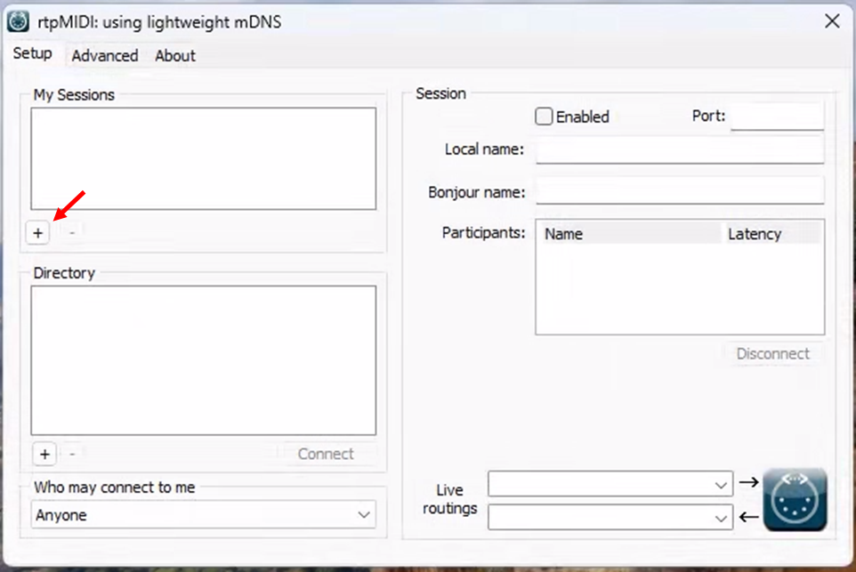
Give the session a name, and press enabled. Make sure that the 'Who may connect to me' setting is set to 'Anyone'. 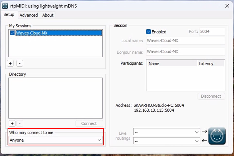
Open the Cloud MX software, and go to the 'Setup' menu. Add a new Mackie controller. And open its settings window.
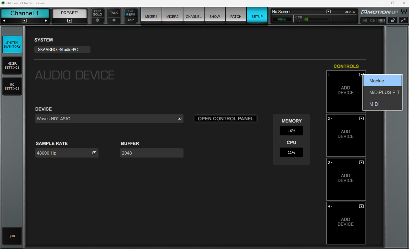
Set the input and output port on Device 1 to match the newly created rtpMIDI session. Enable the 'Jog Wheel Adjust Selected Controls' setting, and if wanted, the 'Follow Aux-Sends' flip.
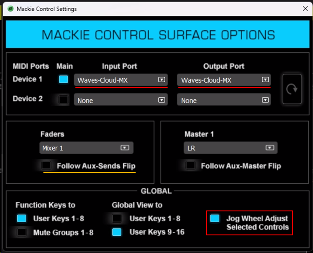
Open reactor on your Skaarhoj device. On the home screen, click the 'Add Device' button on the right side of the screen.
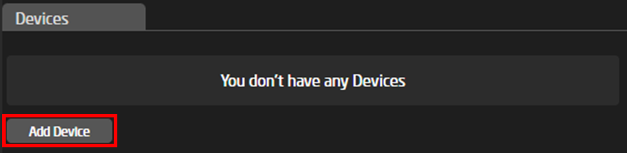
Go to the 'Add Manually' tap and search for 'Waves'. If nothing shows up, enable the 'Show Concepts' setting. Select the Waves Cloud MX device.
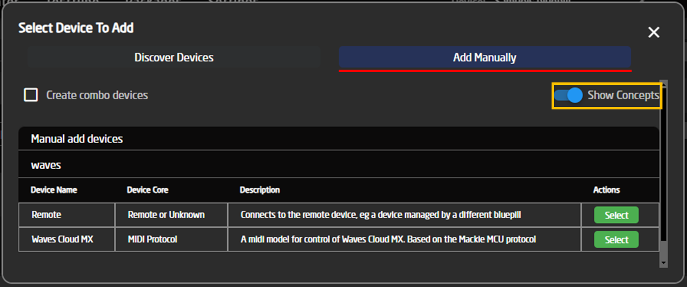
Enter the public IP of your Waves Cloud MX instance, and check that the Remote Port matches the port of the RTP midi session created earlier. In most cases, the default port of 5004 is correct.
[](https://wiki.skaarhoj.com/uploads/images/gallery/2024-11/fNMimage.png)
Confirm that the device is connected. If not, check that the IP and port is set correctly, and that your Skaarhoj device is connected to the internet.
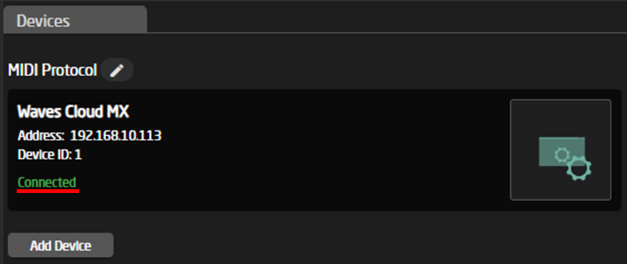
On your Waveboard, select the 'Waves Cloud MX' configuration.
[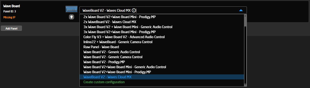](https://wiki.skaarhoj.com/uploads/images/gallery/2024-11/WSnimage.png)
Now you should be all set to use your Waveboard with Waves Cloud MX.
[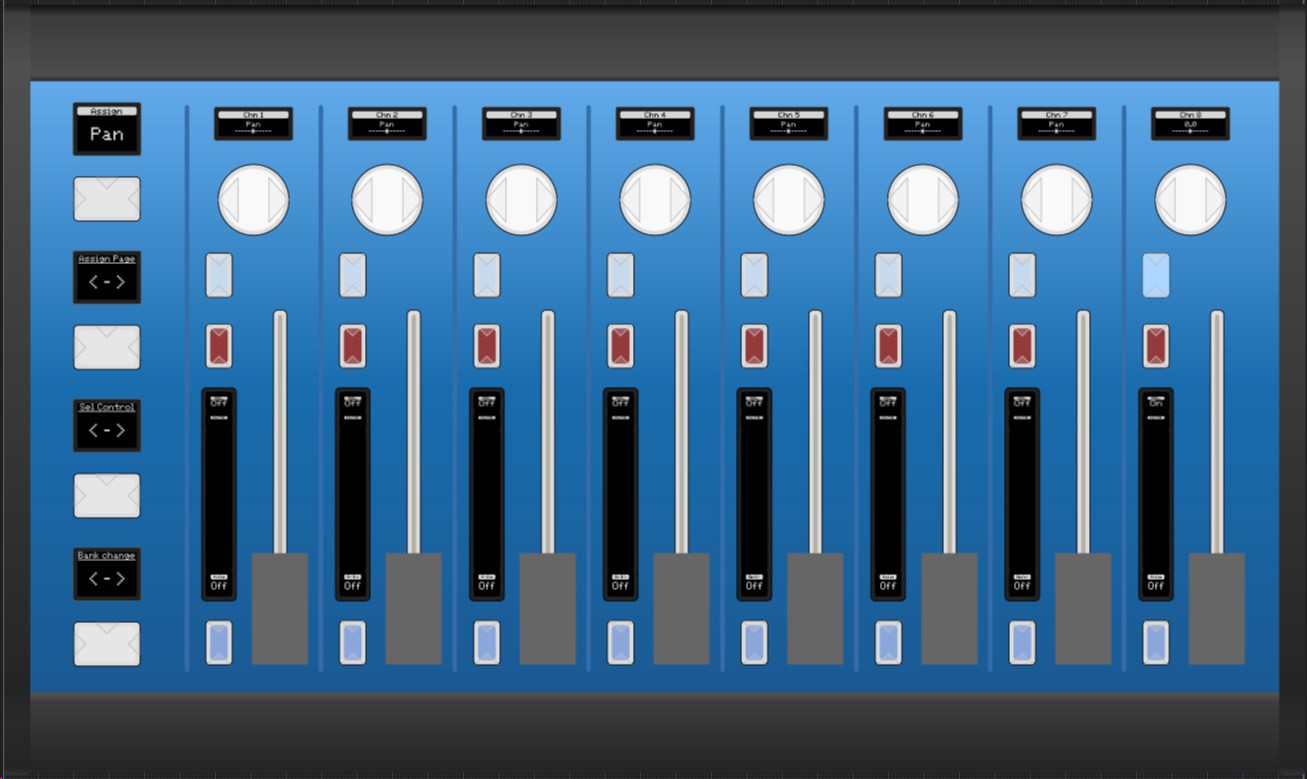](https://wiki.skaarhoj.com/uploads/images/gallery/2024-11/OXdimage.png)
Adding an additional Waveboard
To use two Waveboards at once, you need to add an extra rtpMIDI session. Notice the new port number on the second session.[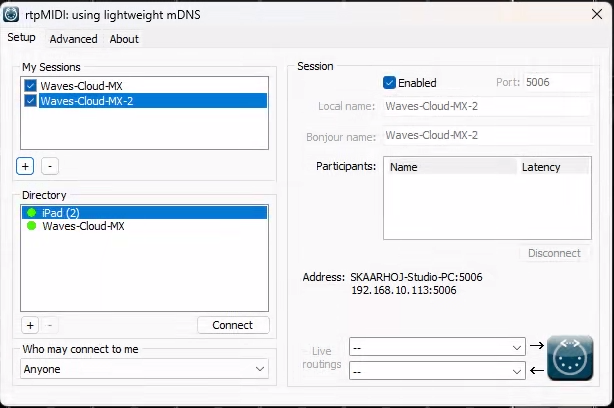](https://wiki.skaarhoj.com/uploads/images/gallery/2024-11/oZnimage.png)
Go to the Mackie Control Settings, and add the new rtpMIDI session as Device 2. Make sure Device 1 is still set as the main device.
[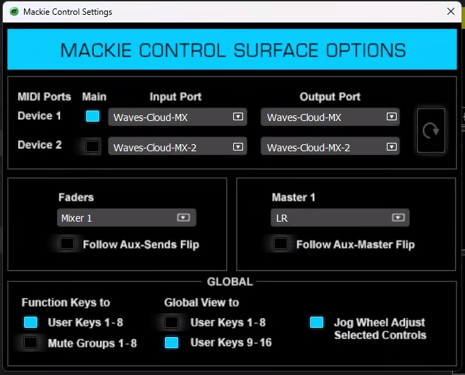](https://wiki.skaarhoj.com/uploads/images/gallery/2024-11/1Plimage.png)
Add an extra Cloud MX device in Reactor on your first WaveBoard. Set the local and remote port to the new rtpMIDI sessions port.
[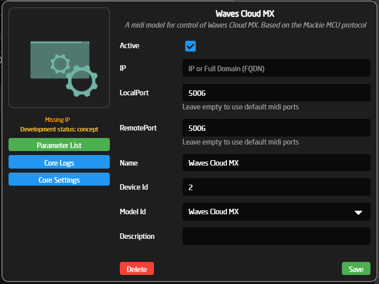](https://wiki.skaarhoj.com/uploads/images/gallery/2024-11/icqimage.png)
Make sure that the 2 devices are set with device ID 1 and 2: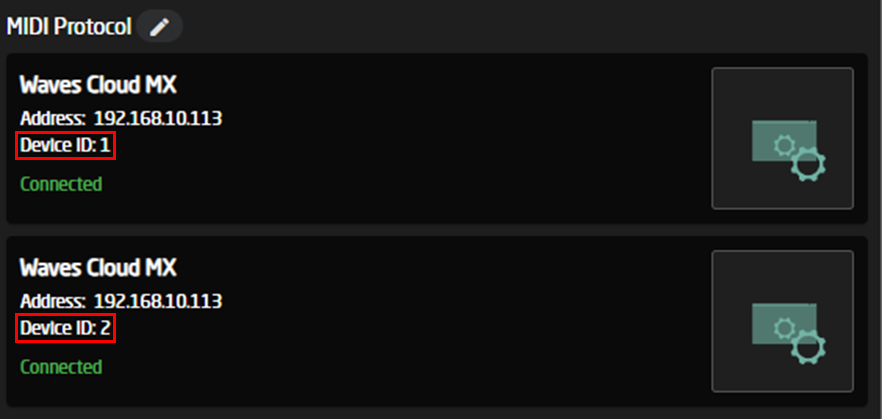
On your second WaveBoard, go to the settings menu, and make sure it is set to 'RawPanel Mode'.
[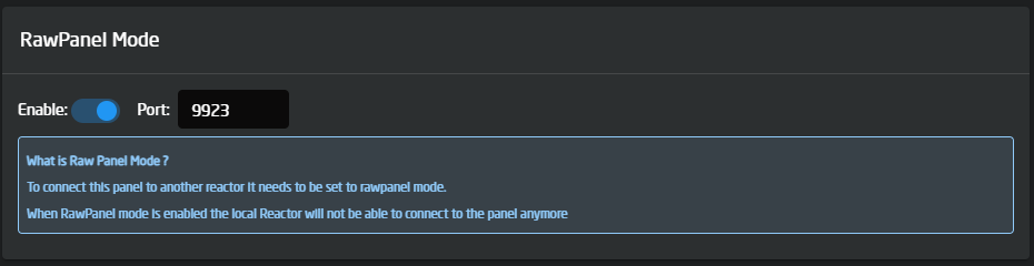](https://wiki.skaarhoj.com/uploads/images/gallery/2024-11/G5jimage.png)
On your first Waveboard, select the '2x WaveBoard V2 - Waves Cloud MX' configuration.
[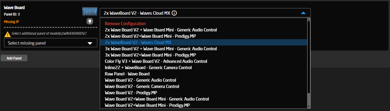](https://wiki.skaarhoj.com/uploads/images/gallery/2024-11/Q9rimage.png)
Press the 'Select missing panel' and 'Add new panel'. In the 'Discover Panels' menu, your second WaveBoard should be shown now, otherwise add it manually.
[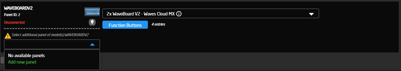](https://wiki.skaarhoj.com/uploads/images/gallery/2024-11/xYVimage.png)
Now you should have 16 channels of control over the 2 WaveBoards.
# Zoom OSC with XPoint24
### **How to set up Zoom OSC**
ZoomOSC is used to managed zoom calls, here is how to set it up
Getting ZoomOSC
Go to the website: [https://www.liminalet.com/zoomosc](https://www.liminalet.com/zoomosc)
[](https://wiki.skaarhoj.com/uploads/images/gallery/2022-05/image-1653657619622.png)
From here you can press **Download Now** It will take you to a form you can fill out, and then you will receive an Email with link to download the Essentials version.
You can also find further instructions, guides, and videos from Liminalet's website!
---
After installing and running the program you will see 2 separate windows.
#### **Window 1:**
Settings window will show you status updates, and allow you to adjust your settings.
[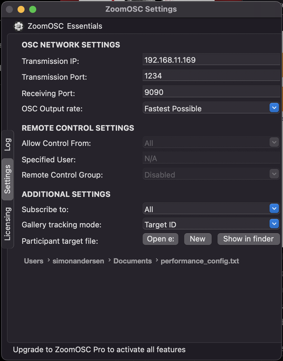](https://wiki.skaarhoj.com/uploads/images/gallery/2022-05/image-1651757250004.png)
It is in the Settings tab you find Network Settings. Take note of these 3 fields:
**Transmission IP** (IP where Zoom OSC will send messages to)
*This should be the Bluepill IP address*
**Transmission Port** (port where Zoom OSC will send messages to)
*This value is used by Reactor to receive information from Zoom OSC*
**Receiving Port** (port where Zoom OSC will listen for messages)
*This value is used by Reactor to send information from Zoom OSC*
#### **Window 2:**
The other window will allow you to join a Zoom meeting or webinar.
[](https://wiki.skaarhoj.com/uploads/images/gallery/2022-05/image-1651756678660.png)
Setup - Zoom OSC with XP24
### **Zoom OSC with XP24:**
We have created a Zoom OSC configuration for our XP24 panel. This means that everything is taken care of automatically by Reactor.
By standard it's set up to auto populate, meaning that as users join the call they will be assigned a button. From there you have full individual control. You will have settings like, toggle mute and video, and more advanced settings like if the attendee is in spotlight or pinned. And all of these settings is right at your fingertips!We have made it easy to change settings for all your attendees by making dynamic user commands.
#### Step-by-step
Step 1
**Install Zoom OSC**
If you haven't already now is the time to download and install the Zoom OSC software
[https://www.liminalet.com/zoomosc](https://www.liminalet.com/zoomosc)
Works on MacOS and Windows 10
Step 2
**Install package**
To control Zoom OSC from a Skaarhoj controller go to your bluepill via reactor. Navigate to the Packages tab and search for “Zoom OSC”
Step 3
**Add Device**
When the devicecore is installed correctly you can now search for “Zoom OSC” in the Device tab from Home. Difference forZoomOSC Essentials
- Choose this device if you only use the free version of Zoom OSCZoomOSC Pro
- Choose this device if you have a paid licence for Zoom OSCZoomOSC Pro Advanced
- This has extra features, but isnt fully supported yet
Step 4
**Setting up the Device**
**IP address:**
This IP address should be the PC running Zoom OSC
**Receiving Port & Transmission Port:**
Find ports in Zoom OSC Networking SettingsThe value Transmission Port in Zoom OSC should be the Receiving in Reactor
The value Receiving Port from Zoom OSC should be the Transmitting in Reactor
Step 5
**Adding Panel & choosing the right configuration**
Make sure the XP24 is turned on. Now it should say “Waiting for raw panel”, and display its IP address In Reactor you can now press Add Panel. Search or find your XP24 panel. If it's not automatically detected you can choose to manually add it. Go to the tab “Add Panel Manually”When added you can make sure the configuration is set to ZoomOSCAnd now the panel will display one message “Meeting OFF”, meaning that is has connection to Zoom OSC on your computer and waiting for you to start a video meeting
Control - Zoom OSC from XPoint24
### **How to run Zoom OSC from XPoint24**
Here is a run-through of the standard configuration for Xpoint24Global Settings
The first thing you will see when you start the meeting is global settings in the top row, and a user row on the bottom.[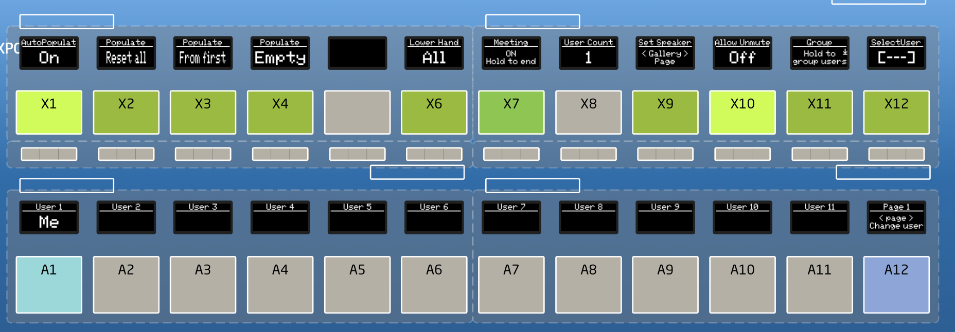](https://wiki.skaarhoj.com/uploads/images/gallery/2022-05/image-1651753663068.png)
- **Auto Populate**
This is on by default, and therefore the Host user has been assigned slot User 1. When Auto populate is active, attendees will automatically get assigned a button from the lower row. This can be set to be default or not in the core config.
- **Reset all**
This button resets all the attendee buttons.
- **From first**
This button resets all the attendee buttons, and populates them randomly from the beginning.
- **Empty**
This button puts all the attendees that are not on buttons already, on the next free buttons. This is helpful, if you do not want to use Auto Populate, but needs to get a lot of attendees down on buttons easily.
- **Lower hand All**
This gives the ability to lower all raised hands from one button
- **Meeting - Hold to end**
Hold for X seconds, and the meeting ends for all user
- **User Count**
Here you can see how many attendees is in the meeting
- **Set Speaker/Gallery** The top of this button changes the view state between speaker and gallery view. When in gallery view, the sides of the button changes the gallery page.
- **Allow Unmute**
Toggle if attendees should be able to unmute themselves
- **Group**
Grouping attendees can give you the same individual control of users (See Attendee settings), just for a group of attendees. To group attendees, hold this button, and press the attendees you want to group.
- **Select User**
This can be used by placing a 'Selected User' on one of the attendee buttons. Then this user can be changed easily by cycling through them on this button. This makes it easier to manage a lot of attendees without having them all on different buttons.Attendee settings
Choose an attendee and now you can toggle settings for that individual.
[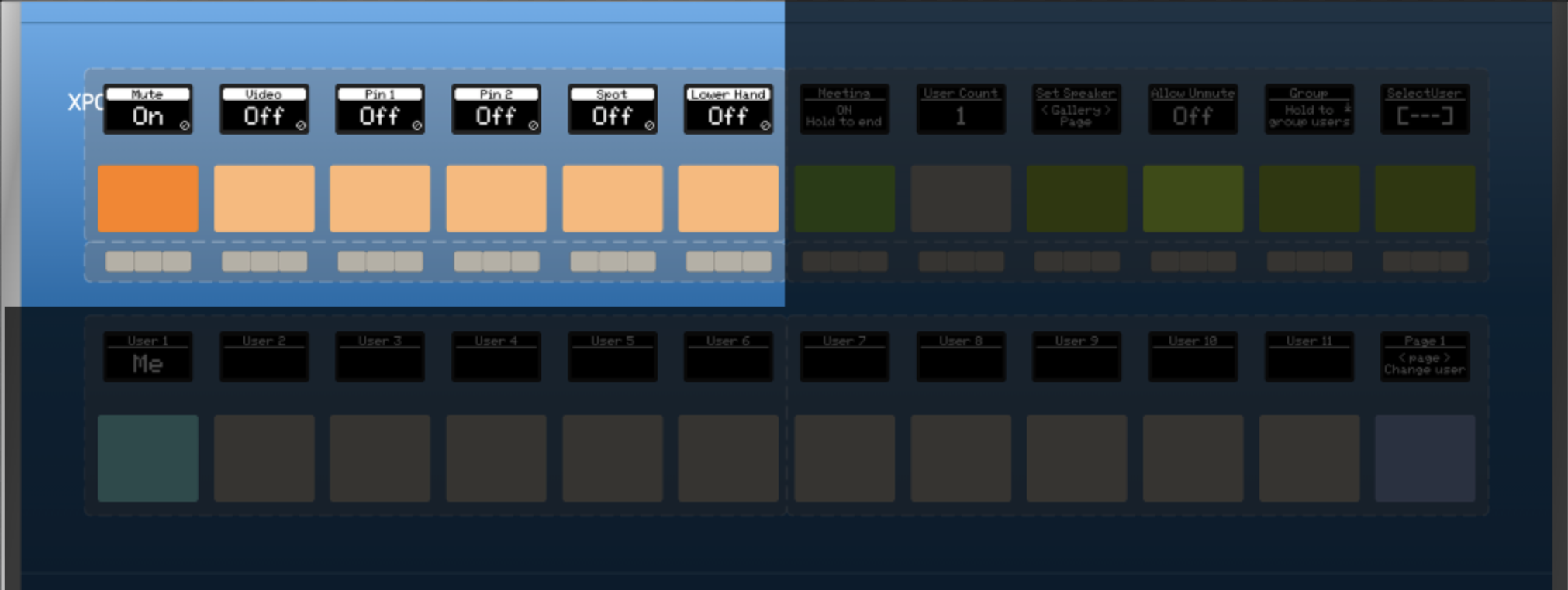](https://wiki.skaarhoj.com/uploads/images/gallery/2022-05/image-1651754090123.png)
- Mute
Toggle Mute for the Attendee (If the Attendee has muted themselves they will get a popup saying the Host has asked them to unmute)
- Video
Toggle Video for the Attendee (If the Attendee has turn off video themselves they will get a popup saying the Host has asked them to turn on video)
- Pin 1 & 2
Host can pin Attendees. This pin will only be visible for the Host
- Spot
Host can spot Attendees. This pin will only be visible for the Host
- Lower Hand
If the Attendee has used the function Raise Hand. The Host has the ability to lower the hand again Troubleshoot
### **Troubleshoot:**
###