DreamChip Camera Setup and Test
These notes will highlight a few cabling workflows and are helpful to connect a DreamChip camera to one of the SKAARHOJ recommended third-party serial converters and perform a functional test of the connection.
Blue Pill Extension Cables vs Ethernet-Serial converter
Notice: The Blue Pill Extension cables are not yet commercially available. Contact innovationlab@skaarhoj.com for more info.
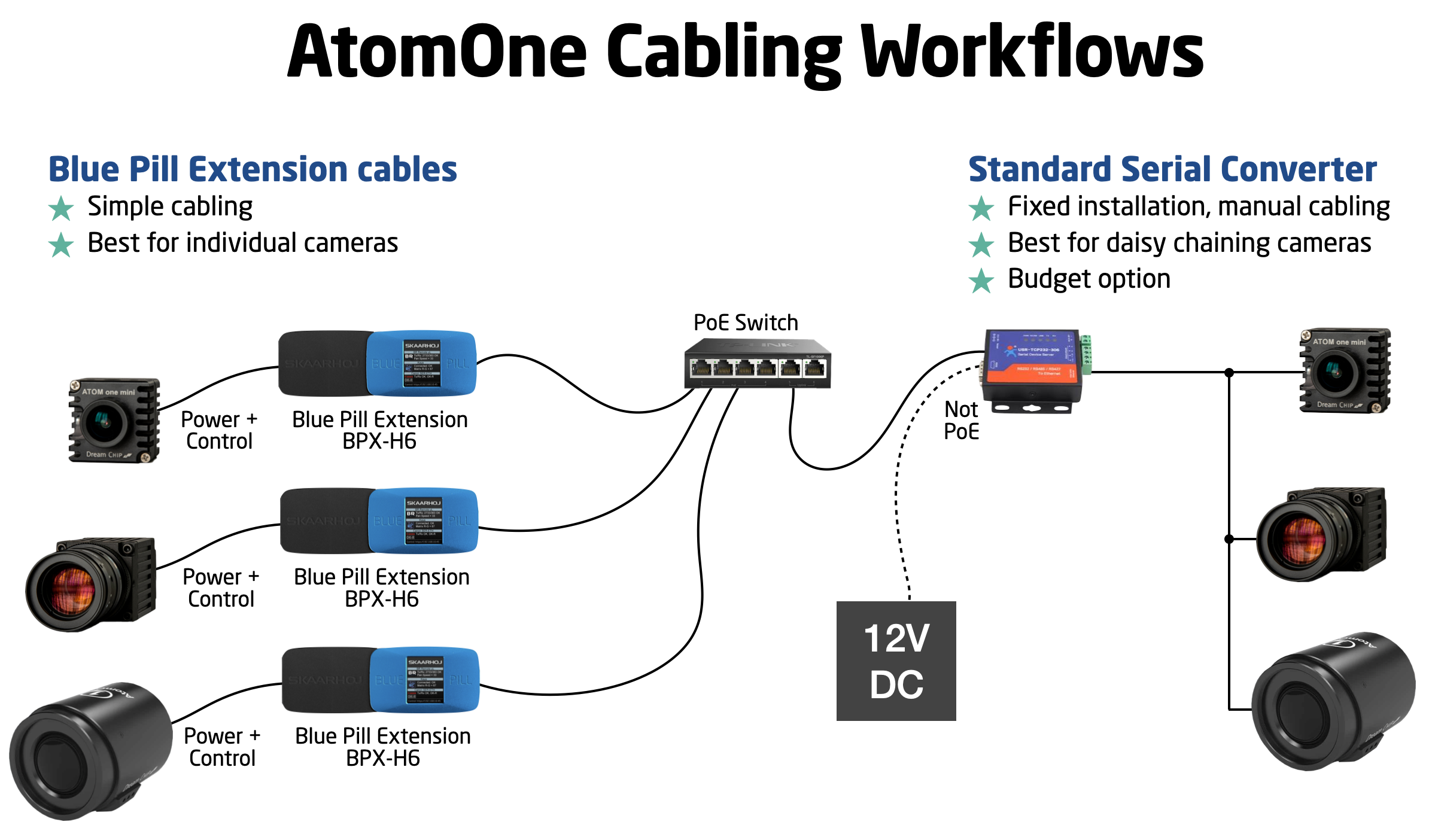
When cabling DreamChip cameras you have basically two options:
- Use a SKAARHOJ Blue Pill as a utility box with the sole purpose of powering and connecting your DreamChip camera. This requires a special extension cable attached to the Blue Pill. This cable connects directly to the Hirose connector of your DreamChip AtomOne camera and supplies power and signal in one. The Blue Pill is powered via PoE and if you purchase the Power version of Blue Pill it (expected availability
in summer 2022)unknown) can power the camera from the PoE+ source. Alternatively the Extension cable has a DC input that is forwarded to the camera.
Using the Blue Pill with PoE+ is an elegant solution and potentially solves other issues too since the Blue Pills software can serve access to the camera for multiple masters via the DreamChip device core running on it. - Use a USR-TCP232-306 or WaveShare RS232/485 Ethernet-Serial
converter.converters. This option requires manual cabling work with screw terminals, possibly some soldering etc. This may be attractive though if you desire to daisy chain the cabling to your cameras.TheTheseUSR-TCP232-306convertersdoes notdon't have PoE so you supply 12V DC to it which can be forwarded to the cameras via the screw terminals. The serial converter has a basic TCP or Websocket interface that the SKAARHOJ controllers device core can connect to. It's important that only one client connects to it and forwards messages since the DreamChip cameras does not have any way to manage multiple masters. Multi master connectivity should always happen by connection to the single DreamChip device core that manages a chain of cameras.
A variant workflow is when a DreamChip AtomOne camera is mounted on a BR Remote Micro L Pan/Tilt head. In this case we recommend a similar workflow, but here the extension cable is different: It has two cables coming out in the other end, one for the camera, one for the BR Remote head:
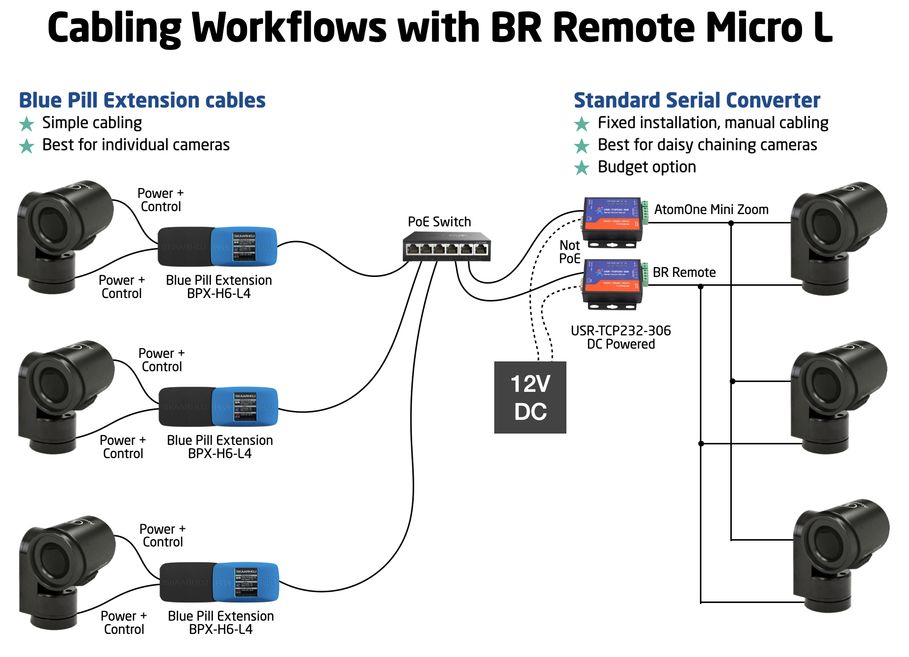
A similar dual extension cable exists for workflows with DreamChip SSM500 and B4 lenses. Ask SKAARHOJ support for guidance.
Finally, you may wonder how to correctly cable a daisy chained set of cameras. This overview may help you:
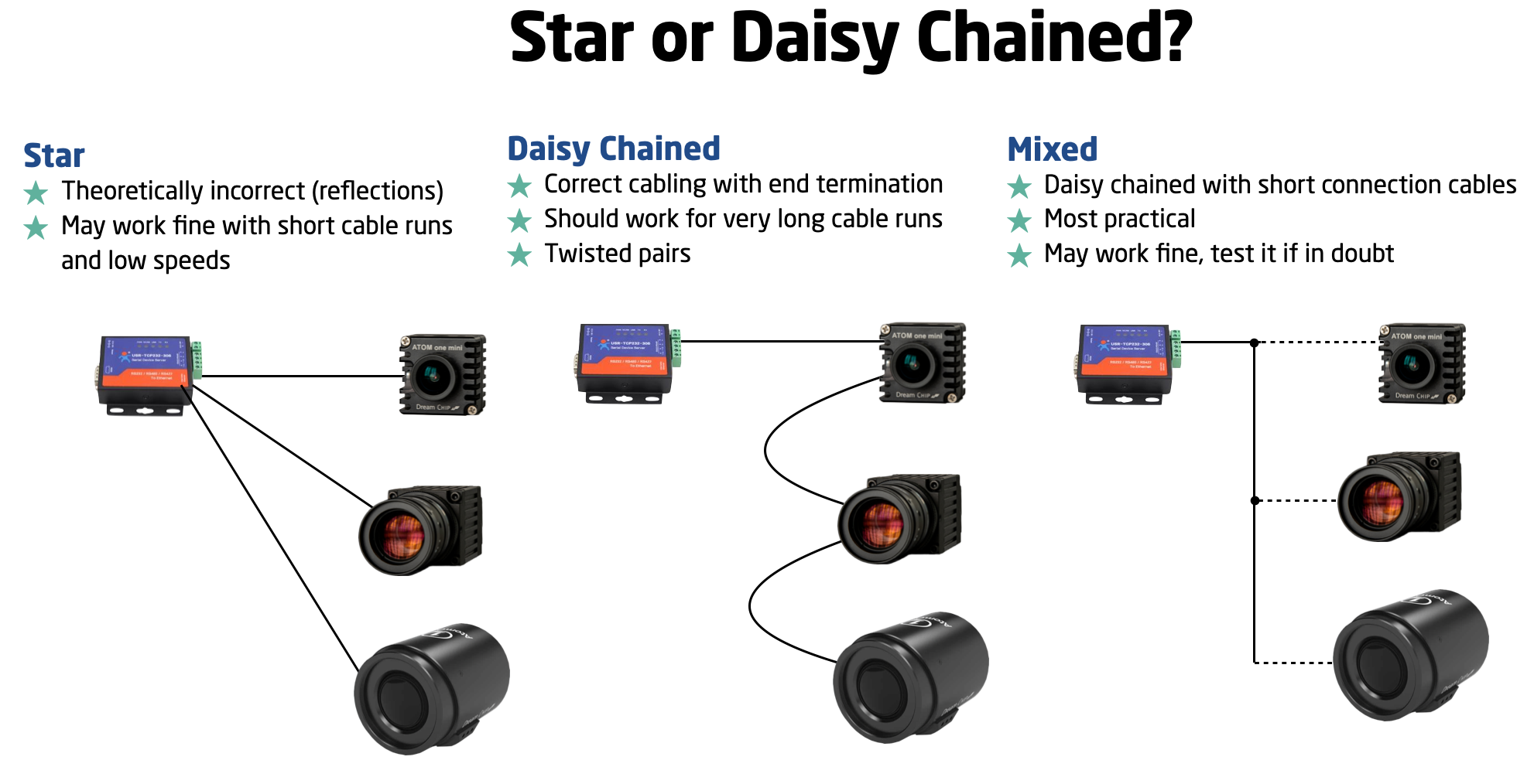
Notice here, that there is the theoretically correct way and then there is very likely room for a little bit of deviation from that. However, SKAARHOJ cannot generally guide you about the limits for that, we just invite you to make your own experience with it.
Working with the serial converter: Cables to camera
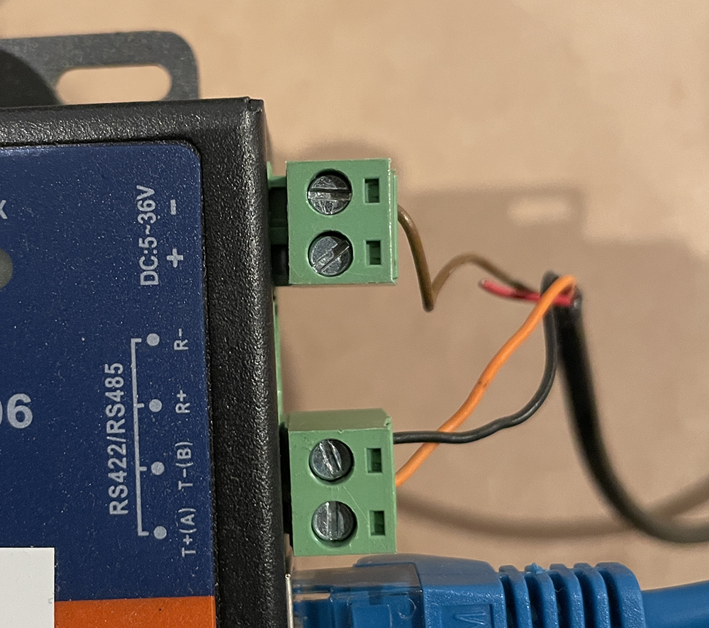
The camera ships with a special cable that connects the Hirose connector on the camera with
- a) 12V Power (Broadcast 4-pin XLR) - Attach this to a 12V power supply
- b) serial RS485 communications (3 Pin female mini XLR) - Attach this to a USR-TCP232-306 Ethernet-Serial converter on T+(A) = orange (mini XLR pin 1), T-(B) = black (mini XLR pin 2) and GND = brown (mini XLR pin 3)
Ethernet-Serial converter
Follow instructions for the Ethernet-Serial converter to get it onto your network. When done, make sure to provide it this Serial setup for operation with the DreamChip camera:
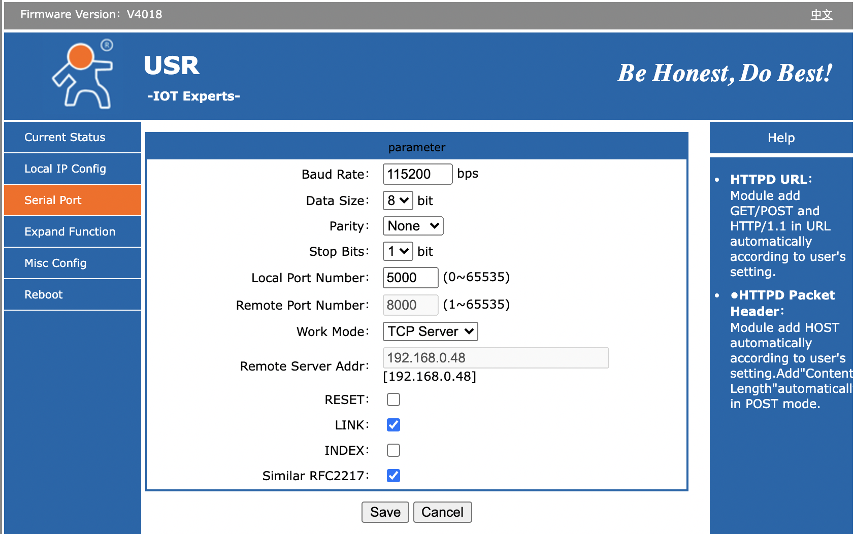
- Baud Rate: 115200
- Data Size: 8 bit
- Parity: None
- Stop Bits: 1
- Local Port Number 5000
- Work Mode: TCP Server
Bug on USR-TCP232-306: It looks like the red TX and green RX LEDs on top of the unit is labeled wrong: On one or more of the units we have tested, it's clear that RX will blink green as we send out content on the serial bus and TX blinks red as we receive content. It feels more intuitive that the TX LED should blink in that case (and vice versa).
The "Link" LED will light up when the device has a network connection. It may not turn of if you pull the plug though - apparently it won't detect such a disconnect.
Test connection
Open a terminal and use "nc" (netcat) or telnet to connect to the converter on port 5000. Using "nc" will send LF as line ending. The camera (SSM-500) has proved to respond correctly to both "LR" and "CRLF" line endings. When connected, you won't receive any greeting, but type in "100 identify" and press enter and you should see the camera answer back. Will look like this:
kasper@Kaspers-MBP-2 ~ % nc 192.168.10.48 5000
100 identify
id: caterham_hs 1 0 0 ATOM one SSM500
OK
Here, we're connecting to converter on IP 192.168.10.48. The blue tekst is the command to the camera, the red is the cameras response back to us. This response shows that the camera has ID = 1 (bold). If multiple cameras were on the serial bus, you would see more cameras respond and announce their ID. This is an example with ATOM One, ATOM One Mini and ATOM One Mini zoom on the same serial bus:
100 identify
id: xbow 1 0 0 ATOM one
OK
id: cooper 2 0 0 ATOM one mini
OK
id: blackline 3 0 0 ATOM one mini Zoom
OK
Notice: The converter will accept multiple connections over IP, but the responses from the camera(s) will be returned to all clients regardless of whether they were the sender of a command. The DreamChip cameras are NOT designed to work with multiple masters, so make sure that only one connected client over IP is talking to the camera - any other clients should only listen to the conversation (if that is even useful for them). If you desire a multi master workflow with DreamChip, you should use a SKAARHOJ Blue Pill with the DreamChip device core which will provide a multi master interface with the SKAARHOJ device core protocol.