DreamChip Camera Setup and Test
This guide outlines cabling workflows to connect DreamChip cameras to SKAARHOJ-recommended third-party serial converters and test the connection.
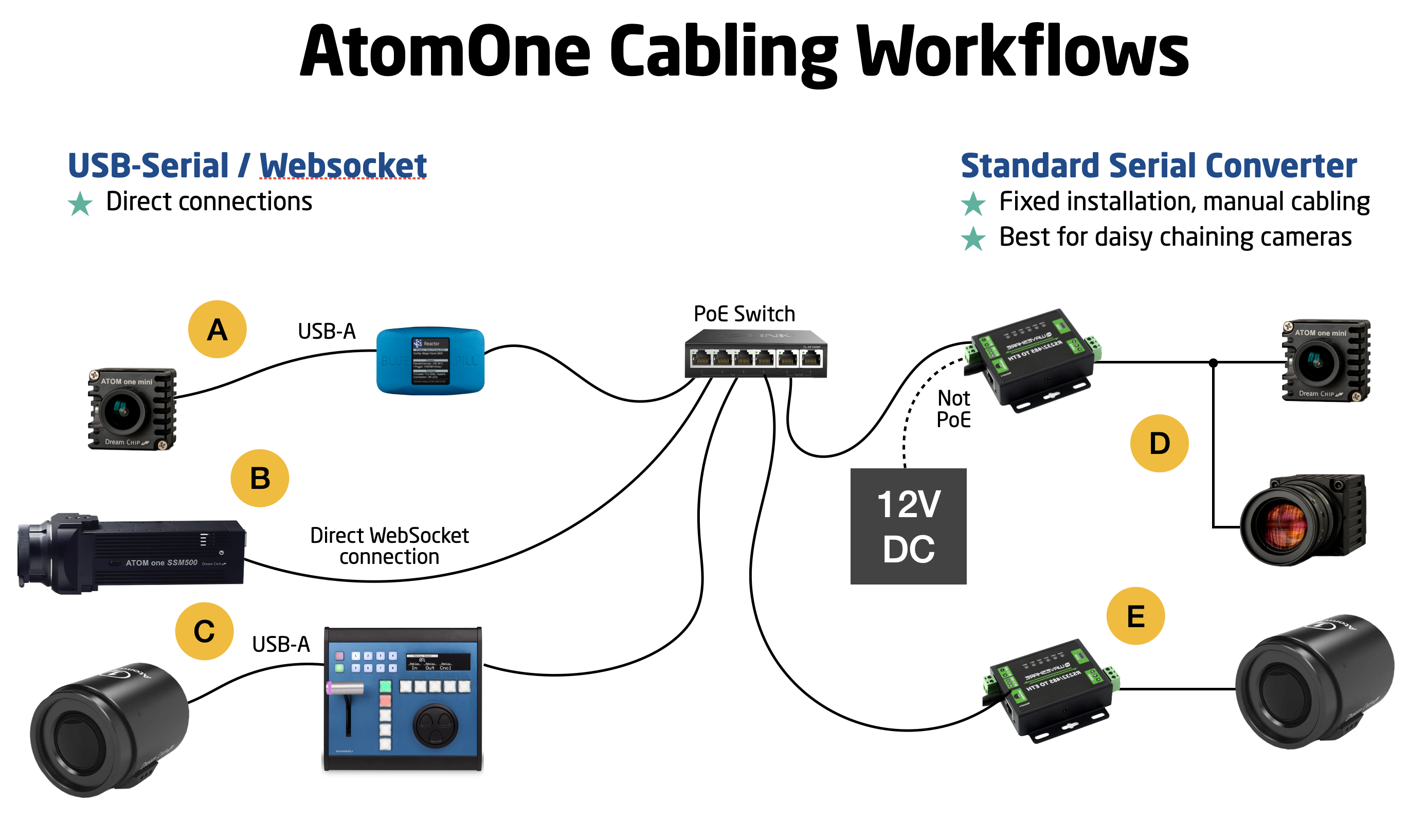
Cabling Options for DreamChip Cameras with SKAARHOJ Control
-
Ethernet-Serial Converter:
- An affordable device connects to your network.
- Forwards DreamChip cameras' RS-485 protocol to a TCP server.
- Use DreamChip's standard cables and an additional Mini-XLR male cable for the serial converter.
- Options:
- a. One converter per camera. (E)
- b. Daisy chain multiple cameras on one converter with different RS-485 addresses (advanced). (D)
-
Direct Web Socket Connection:
- Exclusively for the SSM500 model, highly recommended. (B)
-
USB-Serial Cable Connection:
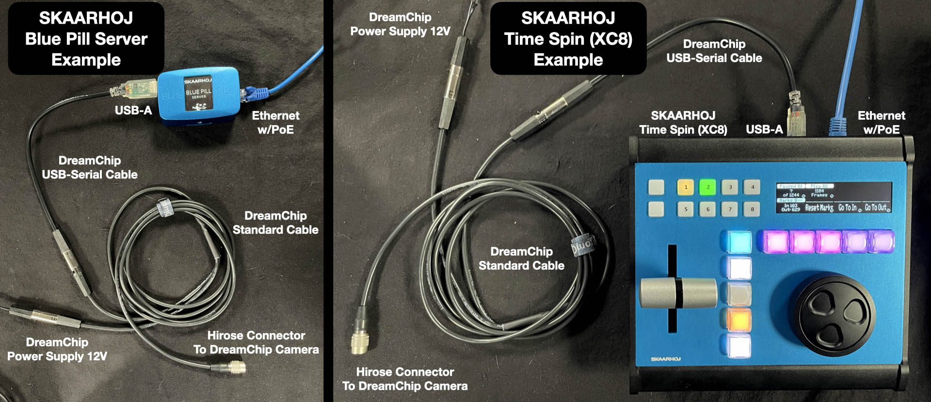
- Connect to SKAARHOJ Blue Pill Server (A) or controllers with USB-A support (e.g., XC8). (C)
- DreamChip provides USB-Serial cables.
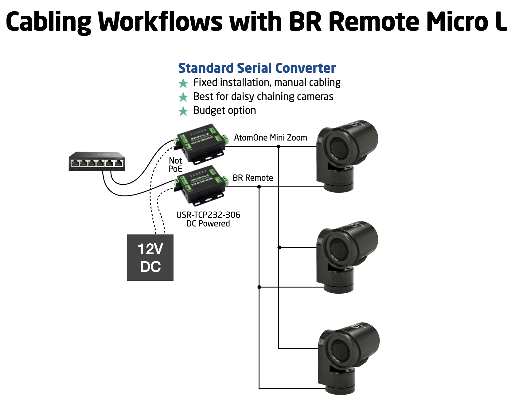
For a workflow involving a DreamChip AtomOne camera mounted on a BR Remote Micro L Pan/Tilt head, we recommend a similar approach:
If you're curious about the proper cabling for a daisy-chained camera setup, this overview should be helpful:
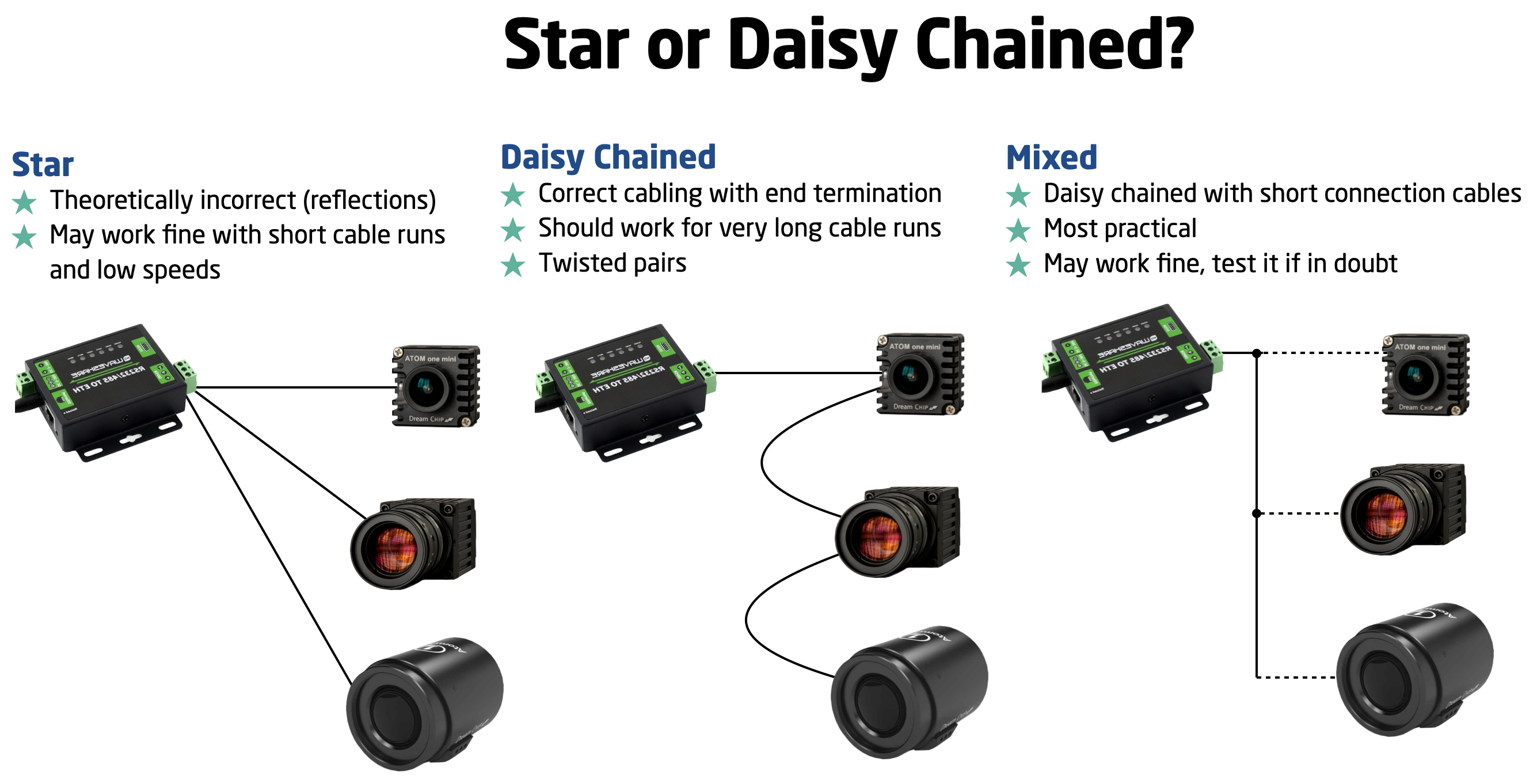
Please note that while there is a theoretical standard for this process, there's often some flexibility for slight deviations. However, SKAARHOJ cannot provide specific guidance on these limits; we encourage you to explore and learn from your own experience.
Setup Video
[A video is on the way....]
USB-Serial
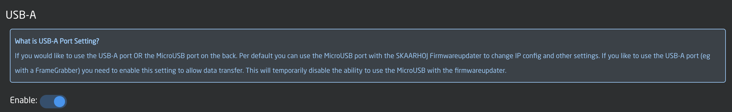
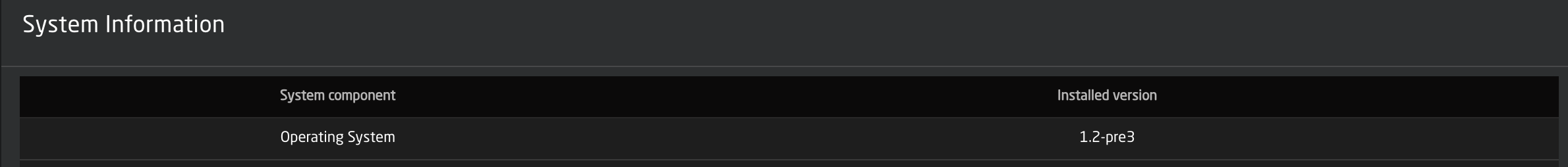
The USB-Serial connection requires a SKAARHOJ device with a USB-A port, available on models like the XC8 and Blue Pill Server. Activate the USB-A port via the controller's Settings page. Ensure your device runs skaarOS version 1.2-pre3 or higher.
For the USB-Serial converter, choose 'USB-Serial' as the connectivity method in the device setup, leaving other fields empty.

Using a USB hub for multiple connections is feasible, though the assignment order may be random upon startup.
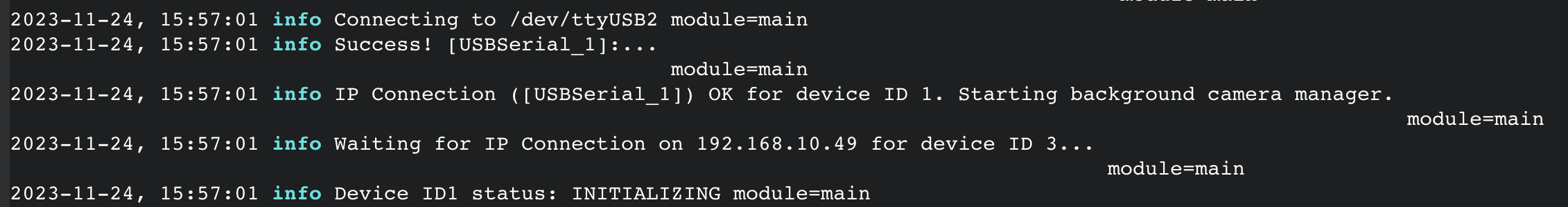
In the core-dreamchip-cam logs, you should see a message like this that confirms connectivity over USB:
Websocket for SSM500
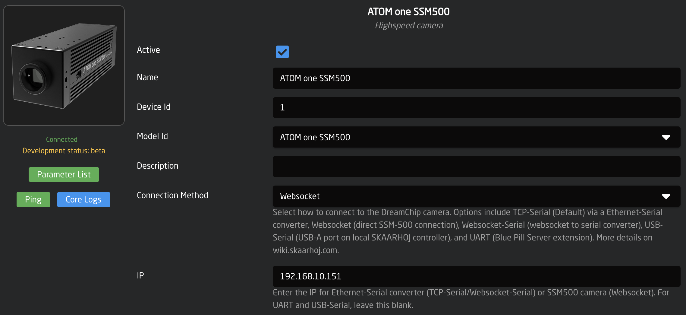
For the SSM500, select 'Websocket' as the connectivity method. This allows the device core to directly connect with the camera. Enter the camera's IP address and leave all other fields blank.
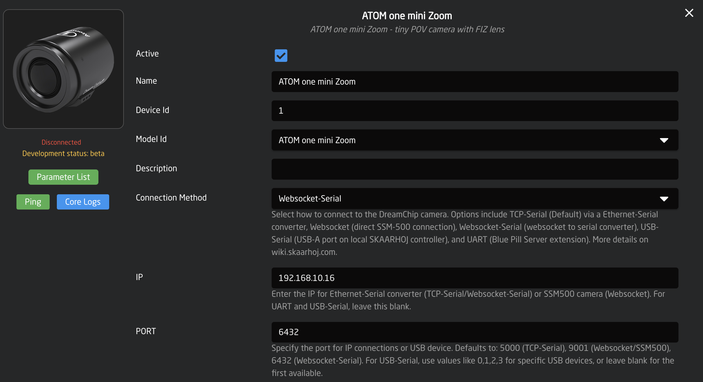
Websocket-Serial
With some firmware versions of the WaveShare RS232/485 Ethernet converter, 'Websocket-Serial' is available as a connectivity option, with the default port being 6432. However, there's no clear advantage of using Websocket-Serial over the more common TCP-Serial, although it is supported as an alternative.
Ethernet-Serial Converters
Set up Ethernet-Serial converters using the 'TCP-Serial' connection method in the device configuration, and include the IP address. Only specify the port if it differs from the default 5000, which should be verified in your serial converter's settings. If using multiple cameras on a single converter, ensure their RS485 addresses are unique. This is adjusted with the 'rs485_addr' command, followed by saving the settings.
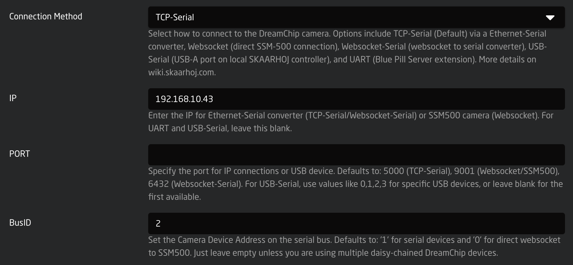
In the example, the BusID is set to '2', which is not typical. Usually, you should leave the field empty as most cameras default to an ID of '1'.
Changing Bus ID (RS485 Address) of a DreamChip camera using the Ethernet converter
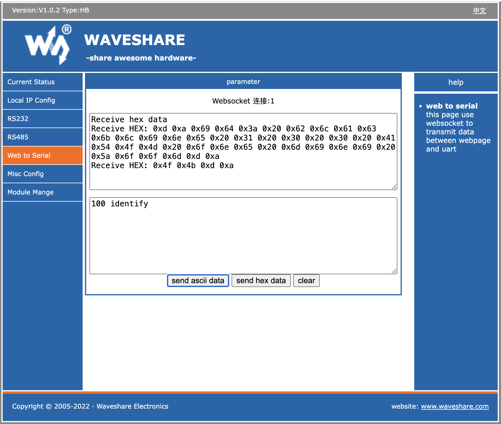
To change a camera's ID on the bus, use a telnet application like Putty, nc, or telnet. Type '100 identify' to see the responding cameras. To change the ID of camera '1' to '2', enter '1 rs485_addr 2', then confirm with '100 identify'. Save this ID change for future boot-ups by typing '2 save_settings' (2 is the new ID!); the camera will reboot. If you encounter issues, consider using DreamChip's ProVideoGUI application for Windows or consult the camera protocol manual.
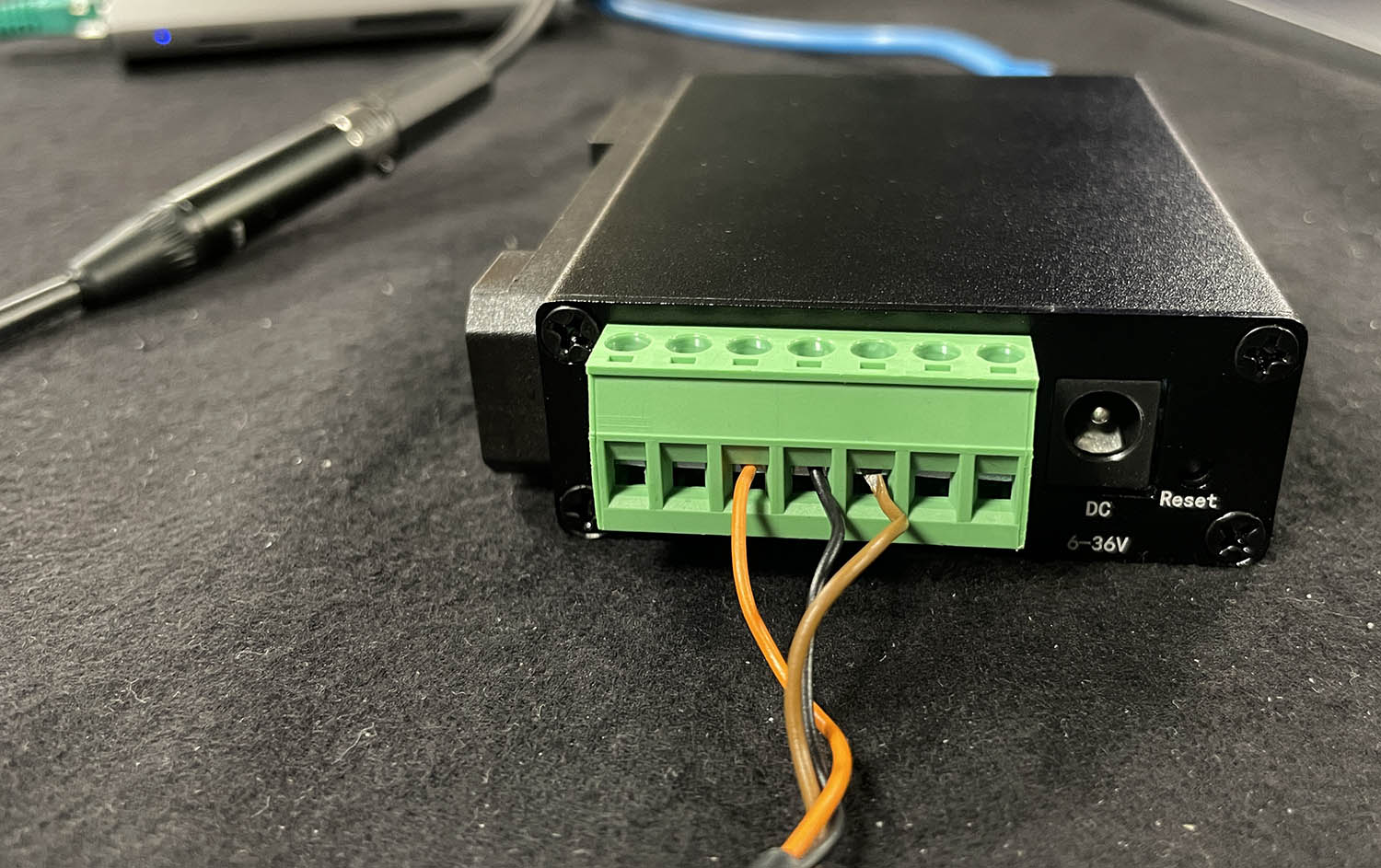
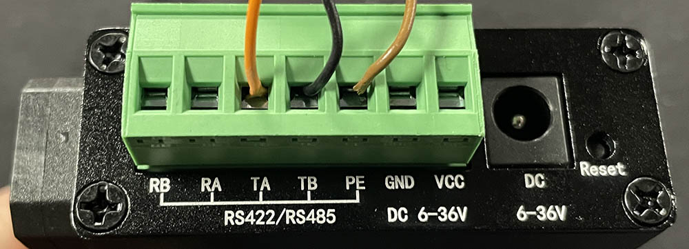
Ethernet-Serial Converter Cabling
Using the standard DreamChip cable is preferred if possible. It's a very simple setup:
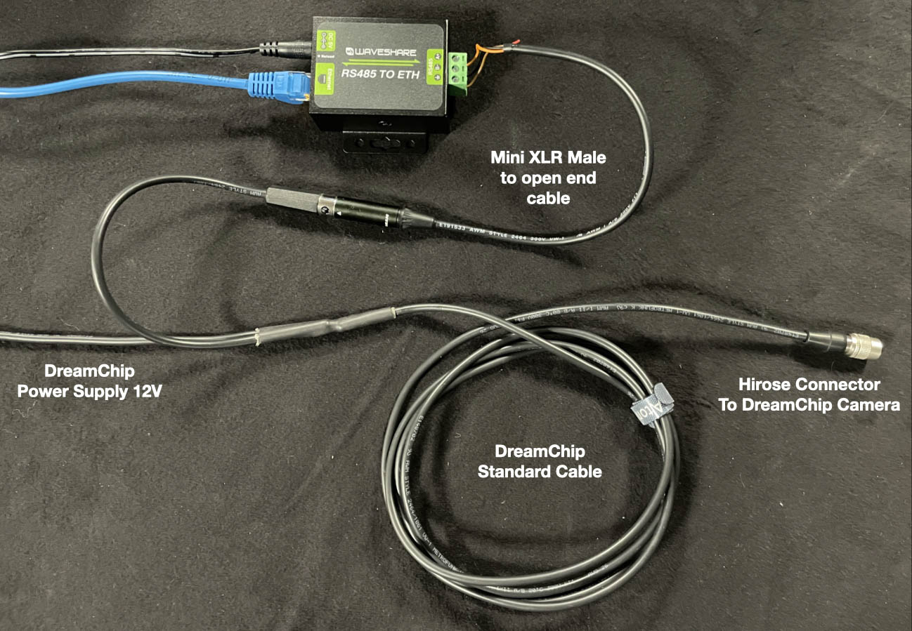
To connect your DreamChip camera to an Ethernet Serial converter of any type, you need a Mini XLR male cable with open wires in the other end. Then you connect it in the following way:
- T+(A) => mini XLR pin 1
- T-(B) => mini XLR pin 2
- GND = mini XLR pin 3
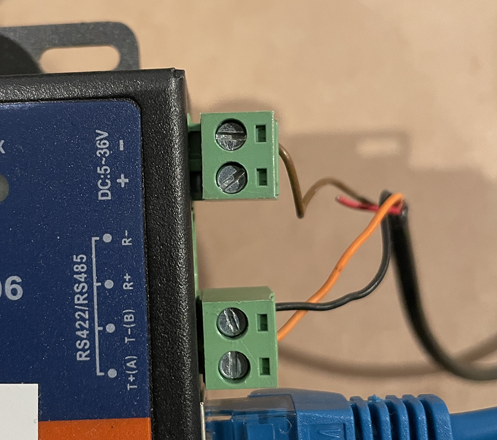
To achieve a multi camera star connection, you simply insert multiple cables in the converter (for short cable runs). You can also use the power passthrough to have one supply to the converter (12V) feed the camera. Be sure to feed 12V into the converter:
Test connection
To connect to the converter using a terminal, employ 'nc' (netcat) or telnet on port 5000. 'nc' sends LF as the line ending, but the SSM500 camera responds to both 'LR' and 'CRLF'. Upon connection, you won’t see a greeting message, but typing '100 identify' and pressing enter will prompt a response from the camera. For example:
kasper@Kaspers-MBP-2 ~ % nc 192.168.10.48 5000
100 identify
id: caterham_hs 1 0 0 ATOM one SSM500
OK
In this instance, we’re connecting to a converter at IP 192.168.10.48. The command sent to the camera is followed by the camera's response. The response indicates the camera's ID (in this case, '1'). With multiple cameras on the same serial bus, each will respond with its ID. Here’s an example with ATOM One, ATOM One Mini, and ATOM One Mini Zoom:
100 identify
id: xbow 1 0 0 ATOM one
OK
id: cooper 2 0 0 ATOM one mini
OK
id: blackline 3 0 0 ATOM one mini Zoom
OK
Note: The converter allows multiple IP connections, but camera responses are broadcast to all clients, irrespective of the command sender. DreamChip cameras are not designed for multiple masters. Only one IP client should actively communicate with the camera, while others may listen. For multi-master setups with DreamChip, use a SKAARHOJ Blue Pill Server with the DreamChip device core for a compatible multi-master interface.
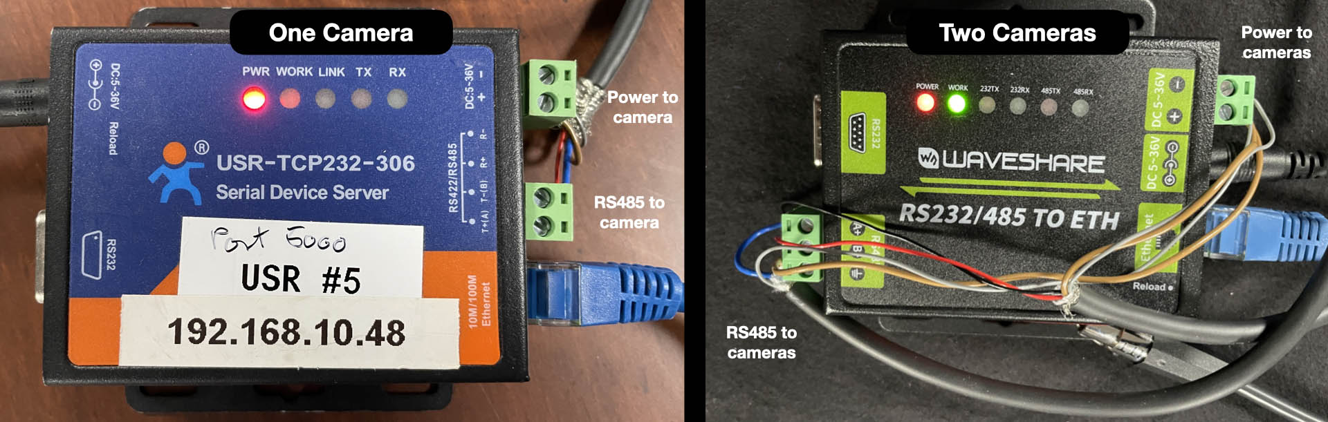
Recommended Ethernet-Serial Converters
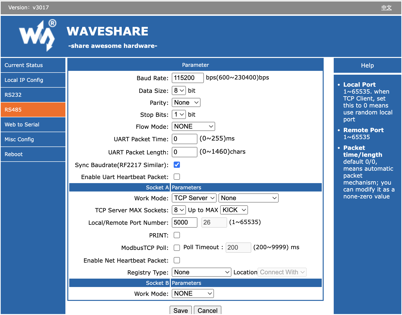
Follow the provided instructions to connect your Ethernet-Serial converter to your network. For WaveShare converters, the default IP is 192.168.0.7. Once connected, configure the Serial setup as shown below for compatibility with DreamChip cameras.
These converters appear to originate from the same factory or brand. While they are not identical and have varying features and behaviors, they most likely represent different iterations of the same platform.
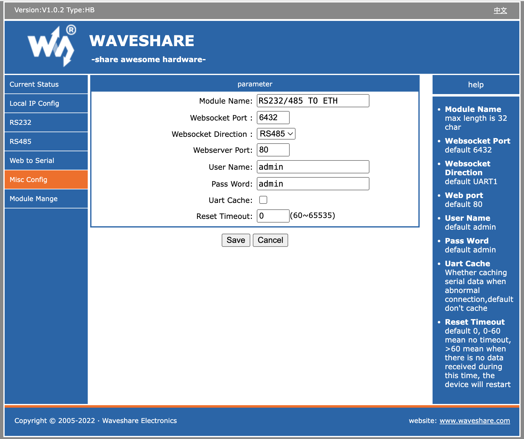
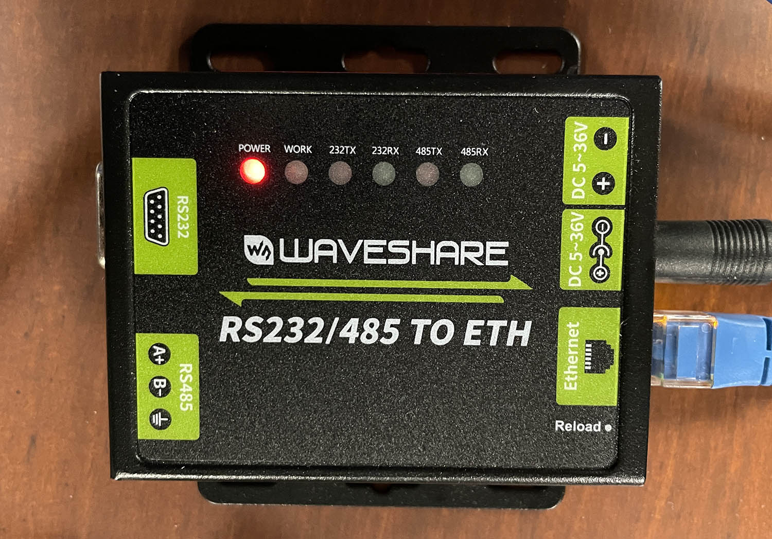
WaveShare RS232/485 To ETH
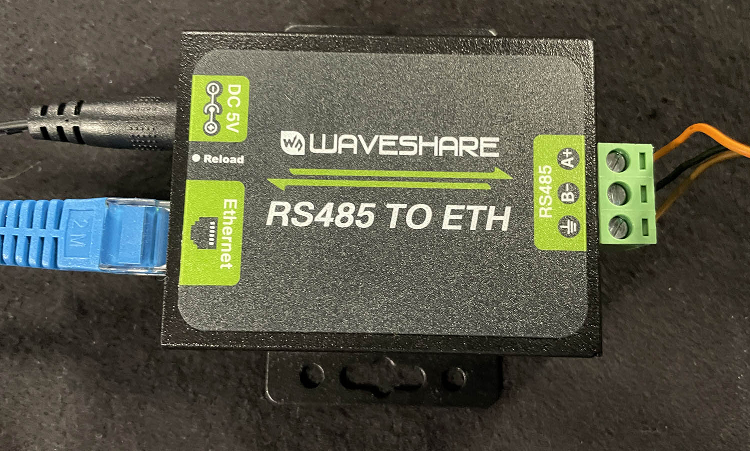
WaveShare RS485 To ETH
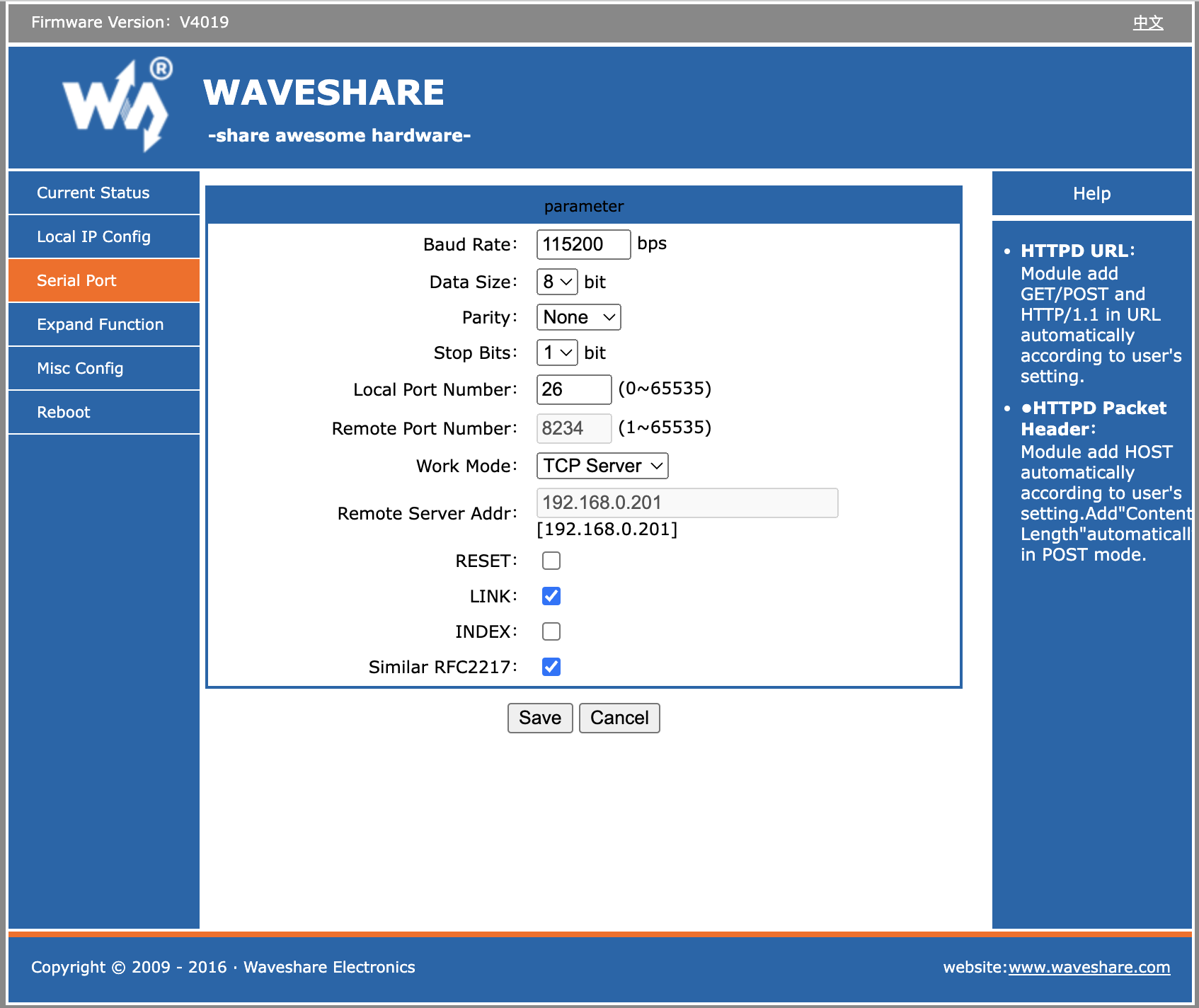
Note: Here we left the port (Local Port Number) at "26". We would normally change this to 5000 to make it compatible with our default values in the device core.
USR-TCP232-306
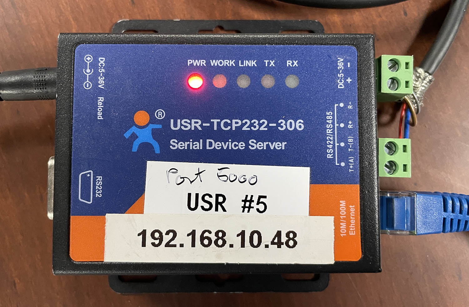
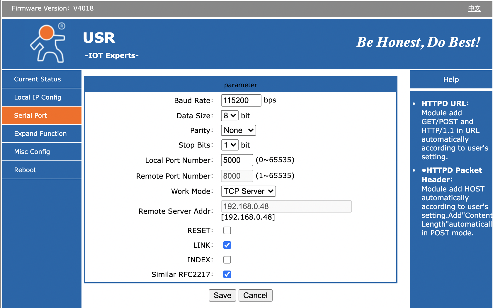
- Baud Rate: 115200
- Data Size: 8 bit
- Parity: None
- Stop Bits: 1
- Local Port Number 5000
- Work Mode: TCP Server
Bug on USR-TCP232-306: It looks like the red TX and green RX LEDs on top of the unit is labeled wrong: On one or more of the units we have tested, it's clear that RX will blink green as we send out content on the serial bus and TX blinks red as we receive content. It feels more intuitive that the TX LED should blink in that case (and vice versa).
The "Link" LED will light up when the device has a network connection. It may not turn of if you pull the plug though - apparently it won't detect such a disconnect.
Other Ethernet-Serial Converter Options
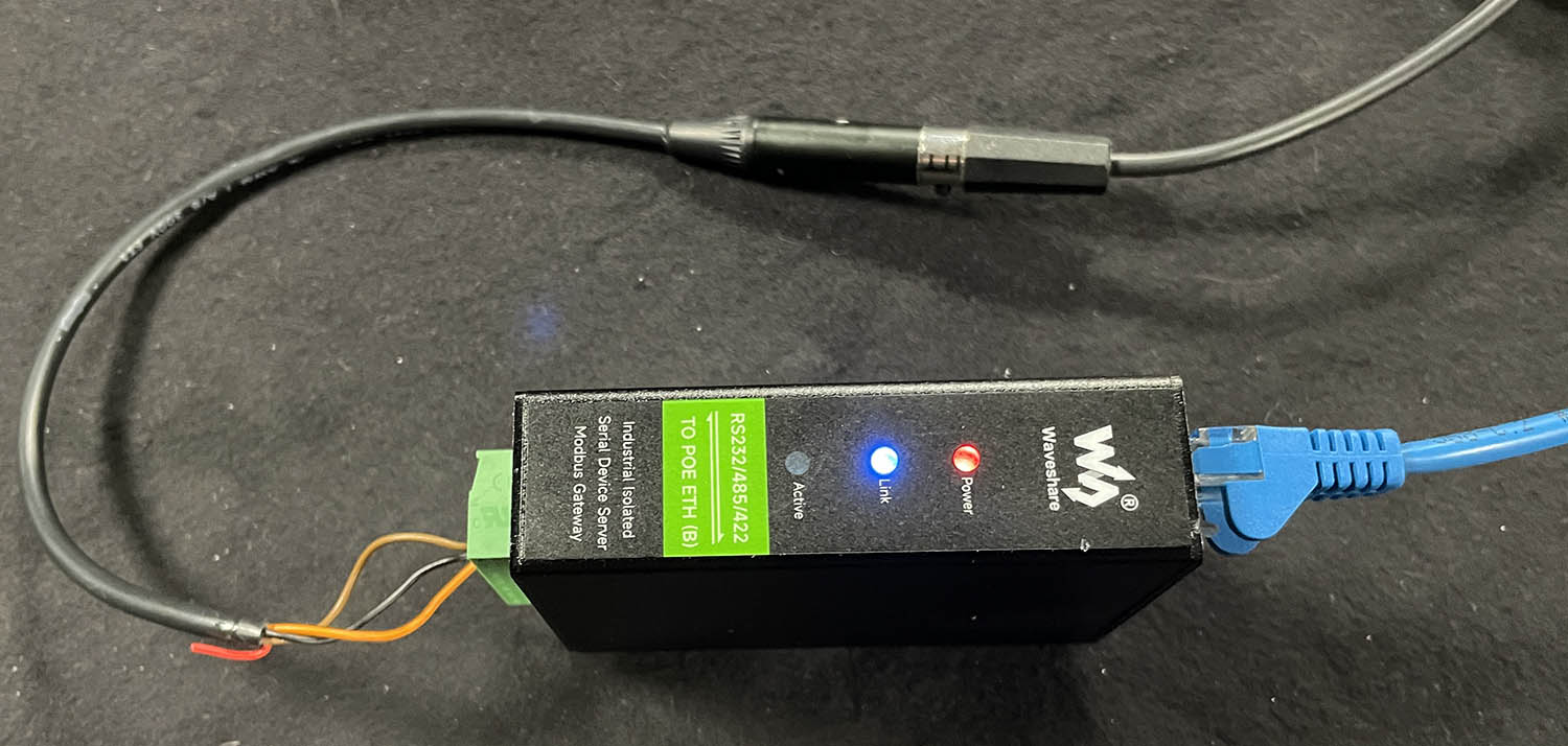
WaveShare RS232/485/422 TO POE ETH (B)
https://www.waveshare.com/rs232-485-422-to-poe-eth-b.htm
https://www.waveshare.com/wiki/RS232/485/422_TO_POE_ETH_(B)
PoE powered converter for DIN rail mounting. Default serial port: 4196 with 115200 baud and tested with ATOM One Mini Zoom. Perfect reconnection on loss of connection. Factory Reset to IP 192.168.1.254.
Note: By default: No web UI on port 80, may need to use Windows tool to configure that!
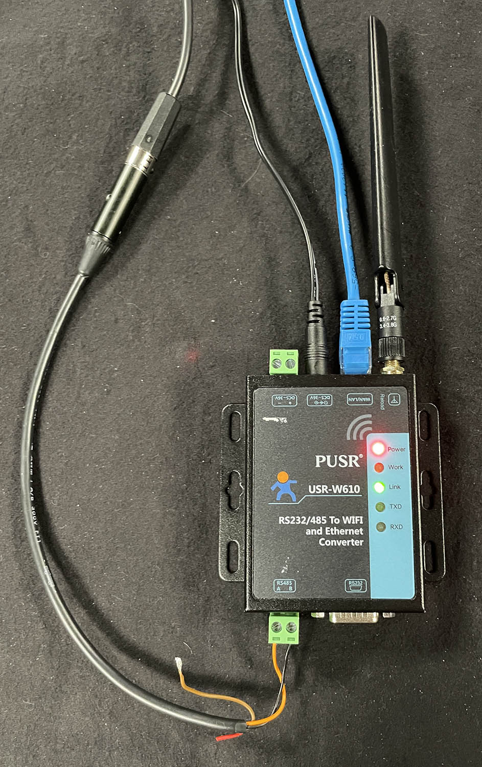
PUSR USR-W610
https://www.pusr.com/download/WIFI/USR-W610-User-Manual-V1.0.1.01.pdf
The device functioned well when connected via cable, but we encountered difficulties in setting up the Wi-Fi. Despite numerous attempts to connect it as a client to my Access Point, we were unable to get the Wi-Fi to work. This issue is particularly significant since the primary purpose of this device is its Wi-Fi capability. Due to this, we cannot recommend it.