DreamChip Camera Setup and Test
This guide outlines cabling workflows to connect DreamChip cameras to SKAARHOJ-recommended third-party serial converters and test the connection.
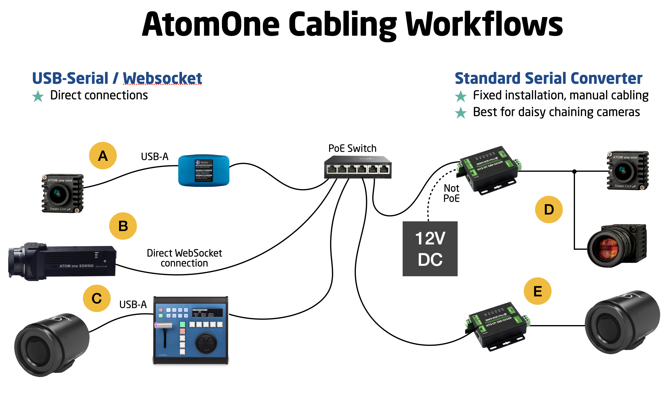
Cabling Options for DreamChip Cameras with SKAARHOJ Control
-
Ethernet-Serial Converter:
- An affordable device connects to your network.
- Forwards DreamChip cameras' RS-485 protocol to a TCP server.
- Use DreamChip's standard cables and an additional Mini-XLR male cable for the serial converter.
- Options:
- a. One converter per camera. (E)
- b. Daisy chain multiple cameras on one converter with different RS-485 addresses (advanced). (D)
-
Direct Web Socket Connection:
- Exclusively for the SSM500 model, highly recommended. (B)
-
USB-Serial Cable Connection:
- Connect to SKAARHOJ Blue Pill Server (A) or controllers with USB-A support (e.g., XC8). (C)
- DreamChip provides USB-Serial cables.
For a workflow involving a DreamChip AtomOne camera mounted on a BR Remote Micro L Pan/Tilt head, we recommend a similar approach:
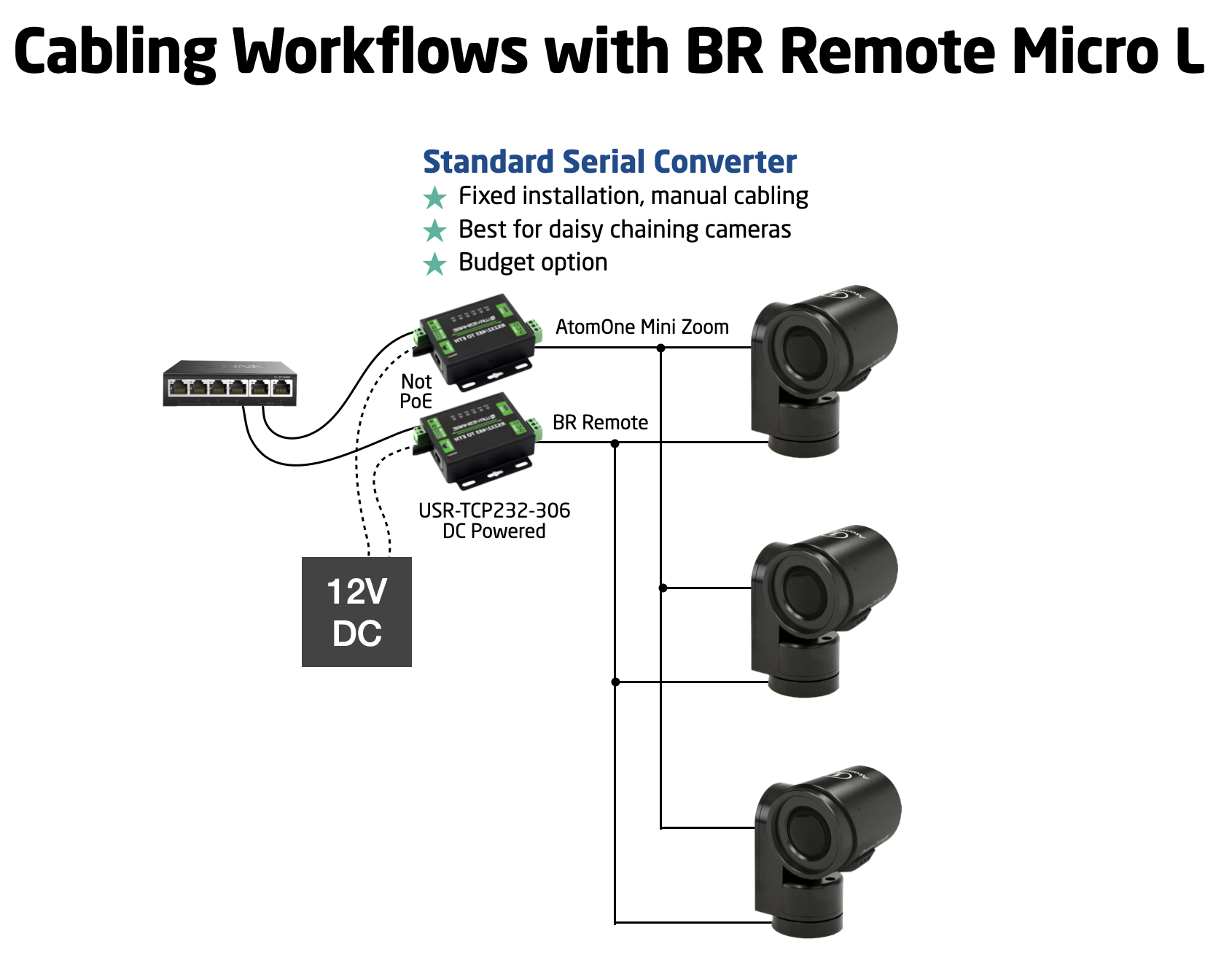
If you're curious about the proper cabling for a daisy-chained camera setup, this overview should be helpful:
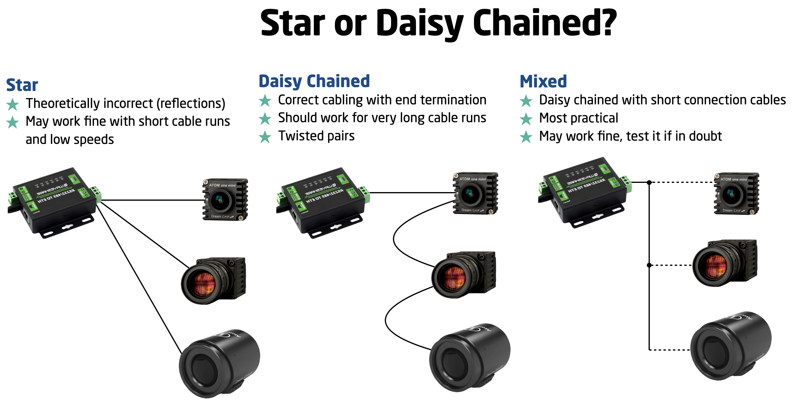
Please note that while there is a theoretical standard for this process, there's often some flexibility for slight deviations. However, SKAARHOJ cannot provide specific guidance on these limits; we encourage you to explore and learn from your own experience.
USB-Serial
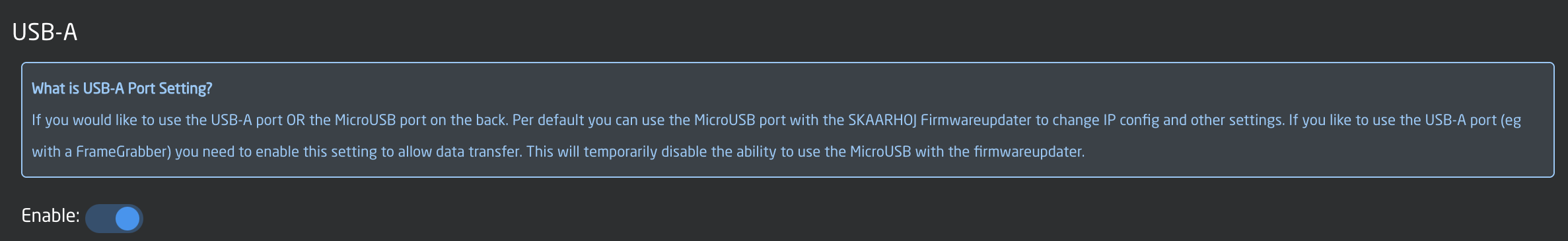
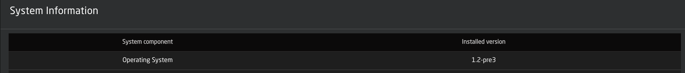
The USB-Serial solutionconnection requires a SKAARHOJ device with a USB-A port.port, This is foundavailable on productsmodels like the XC8 and Blue Pill Server. You must enableActivate the USB-A port insidevia the controllerscontroller's Settings page. Also,Ensure youyour mustdevice runruns askaarOS version of the skaarOS operating system equal to1.2-pre3 or larger than 1.2-pre3.higher.
To use
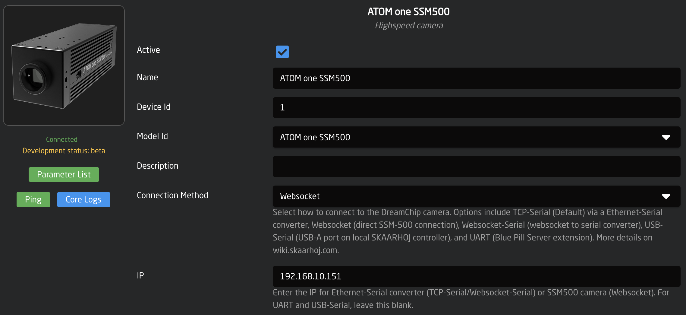
For the USB-Serial converterconverter, youchoose must'USB-Serial' selectas the "USB-Serial" connectivity method in the device setsetup, up.leaving Otherother fields should be blank.empty.
It's
Using a USB hub tofor workmultiple withconnections moreis thanfeasible, onethough USBthe connection,assignment but theyorder may be assignedrandom randomlyupon in order when you boot it up.
startup.
Websocket for SSM500
For SSM500the youSSM500, canselect choose'Websocket' as the "Websocket" connectivity method,method. andThis allows the device core will try to reachdirectly connect with the cameracamera. directly. In this case,Enter the camera's IP address shalland beleave that of the camera. Leave theall other fields blank.
Ethernet-Serial Converter Cabling
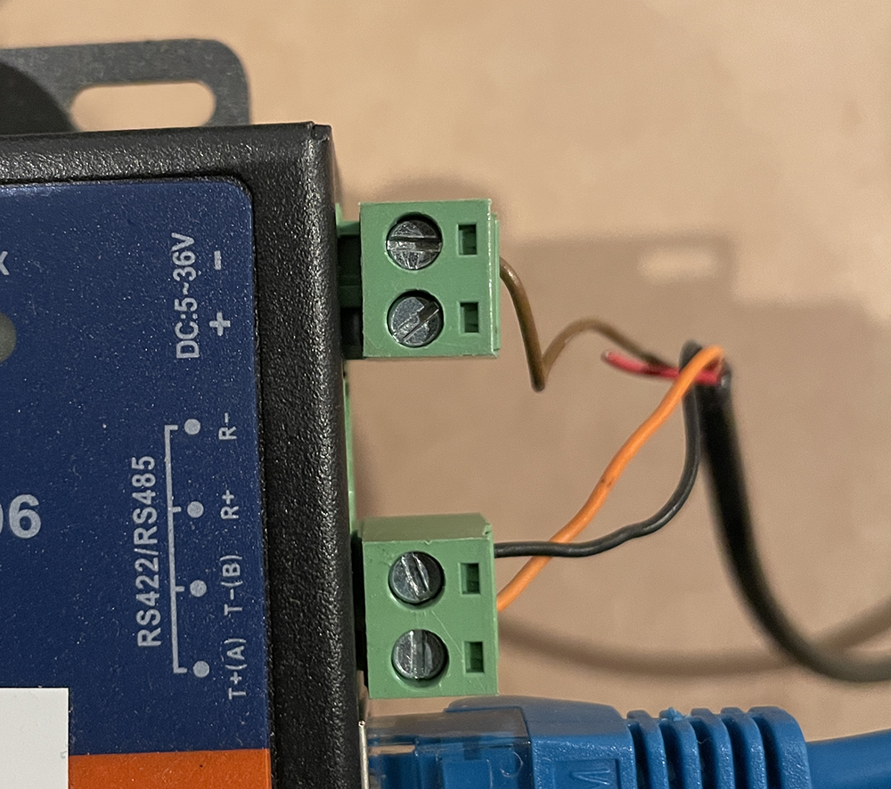
To connect your DreamChip camera to an Ethernet Serial converter of any type, you need a Mini XLR male cable with open wires in the other end. Then you connect it in the following way:
- T+(A) => mini XLR pin 1
- T-(B) => mini XLR pin 2
- GND = mini XLR pin 3
Test connection
Open a terminal and use "nc" (netcat) or telnet to connect to the converter on port 5000. Using "nc" will send LF as line ending. The camera (SSM-500) has proved to respond correctly to both "LR" and "CRLF" line endings. When connected, you won't receive any greeting, but type in "100 identify" and press enter and you should see the camera answer back. Will look like this:
kasper@Kaspers-MBP-2 ~ % nc 192.168.10.48 5000
100 identify
id: caterham_hs 1 0 0 ATOM one SSM500
OK
Here, we're connecting to converter on IP 192.168.10.48. The blue tekst is the command to the camera, the red is the cameras response back to us. This response shows that the camera has ID = 1 (bold). If multiple cameras were on the serial bus, you would see more cameras respond and announce their ID. This is an example with ATOM One, ATOM One Mini and ATOM One Mini zoom on the same serial bus:
100 identify
id: xbow 1 0 0 ATOM one
OK
id: cooper 2 0 0 ATOM one mini
OK
id: blackline 3 0 0 ATOM one mini Zoom
OK
Notice: The converter will accept multiple connections over IP, but the responses from the camera(s) will be returned to all clients regardless of whether they were the sender of a command. The DreamChip cameras are NOT designed to work with multiple masters, so make sure that only one connected client over IP is talking to the camera - any other clients should only listen to the conversation (if that is even useful for them). If you desire a multi master workflow with DreamChip, you should use a SKAARHOJ Blue Pill with the DreamChip device core which will provide a multi master interface with the SKAARHOJ device core protocol.
Ethernet-Serial Converters
WaveShare RS232/485 To ETH
WaveShare RS485 To ETH
USR-TCP232-306
Ethernet-Serial converter
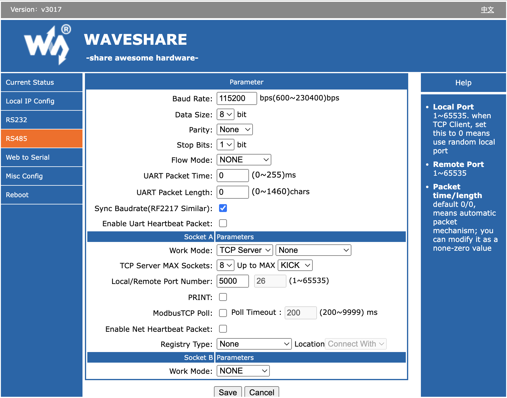
Follow instructions for the Ethernet-Serial converter to get it onto your network. When done, make sure to provide it this Serial setup for operation with the DreamChip camera:
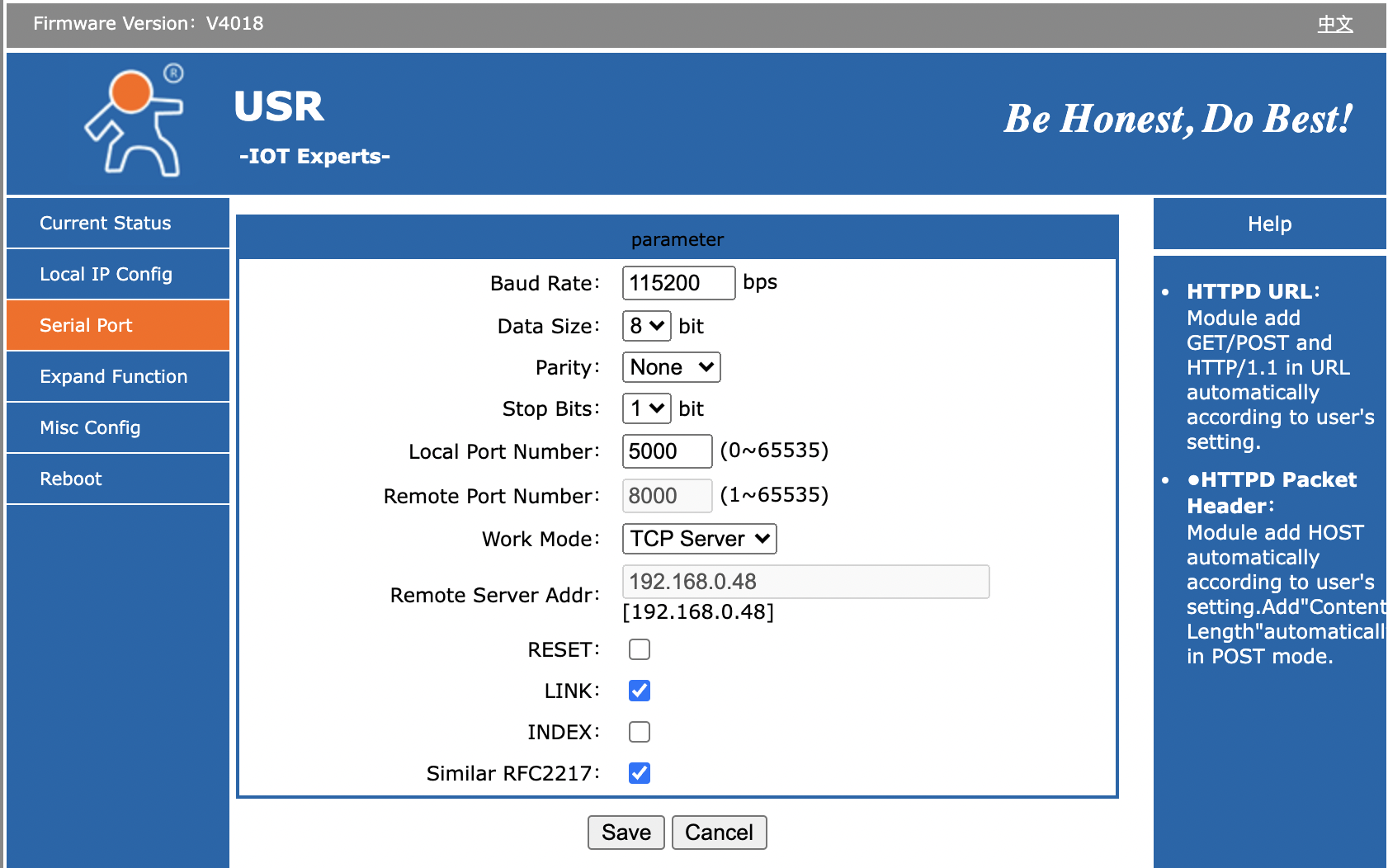
- Baud Rate: 115200
- Data Size: 8 bit
- Parity: None
- Stop Bits: 1
- Local Port Number 5000
- Work Mode: TCP Server
Bug on USR-TCP232-306: It looks like the red TX and green RX LEDs on top of the unit is labeled wrong: On one or more of the units we have tested, it's clear that RX will blink green as we send out content on the serial bus and TX blinks red as we receive content. It feels more intuitive that the TX LED should blink in that case (and vice versa).
The "Link" LED will light up when the device has a network connection. It may not turn of if you pull the plug though - apparently it won't detect such a disconnect.