TCP Device Core / UDP Device Core
The TCP Device Core for Blue Pill, core-protocol-tcp, allows users to send and to some extend receive and process information of TCP to both ASCII and binary servers. Effectively, this can help to bridge communication with devices where a dedicated device core is not available.
The UDP Device Core for Blue Pill, core-protocol-udp, enables the exact same functionality as for TCP, just over a UDP connection.
This page describes how both device cores work, but using core-protocol-tcp as the example. The device cores have both a very basic mode and some more complex features that can come in handy in some cases. It has been designed to align with the corresponding TCP Client device core on the UniSketch platform.
Commands
The commands you can specify and send are ASCII by default and exactly what you see in the string will be sent as ASCII, unless:
- \n and \r will send a newline or carriage return (bytes 10 and 13)
- \xHH will send a byte with the value HH (in hex): so \xFF will send a byte with value “255”
-
\p1, \p2 or \p3 (alternatively \d1, \d2, \d3, \h1, \h2, \h3, \i1, \i2, \i3, \f1/[scale], \f2/[scale], \f3/[scale]) will insert a parameter value as defined by the meta value p1, p2 and p3 in the device core parameters Toggle, On Trigger and Off Trigger.
The difference of using \p, \d, \i, \f and \h is whether the meta value is inserted as the byte value (\p), inserted as a byte decimal number like “255” or “37” or “3” (\d - there is no leading zeros), as a signed 32 bit integer (\i), as a floating point number (\fx/[scale]) or in hexadecimal like FF or D0 or 00 (\h - in this case it’s always two characters and uppercase).
Floating point
Inserting a floating point number with \f is based on the parameter p1-p3 being an integer which gets divided by the [scale] number. For example, if you insert \f2/10 then if meta value parameter p2 is a variable with the value 55, it will get formatted as "5.5" in the message.
Example
Say you want to send a command to fire DMEMs on GVG100, in that case you want to send the text string “03 01 DB 00” to fire DMEM 01, send “03 01 DB 01” to fire DMEM 02 etc.
So setting up a command like “03 01 DB \h1” and then using the “p1” meta value through a constant in Reactor would allow you to distribute the same behavior across multiple hardware components on a panel but vary the Dmem value easily.
Testing and tools
An advice is to use the "ipserver" binary tool provided by SKAARHOJ to set up a server to help testing the functionality until you are confident that everything works as expected and would function with the final target device.
Basic Configuration
The device core has some configuration fields:
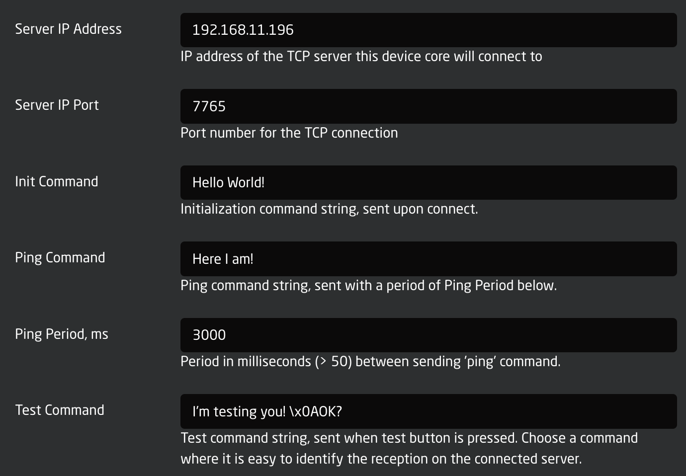
- IP address and port for the server should be straight forward.
- The Init Command is a command string that will be sent to the server one time upon a new connection.
- The Ping Command will be send periodically. The period between its being sent will be 3000 ms in this case.
- The Test Command is send when the Test trigger is activated (that's typically available as a button in Reactor)
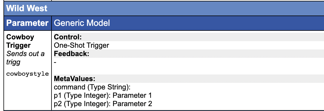
Cowboy Style
The most straight forward way to use the device core would be to send one-shot triggers cowboystyle. This requires the minimum of configuration but provides the least amount of long term convenience. This is probably a good place to get started.
Command Configuration
The device core allows you to configure a number of fixed commands. The advantage is that you can bundle an A and B command into a single action for toggles etc. Also, this is the way you can use meta values with the \p1,\p2, ... placeholders etc. Finally, it's actually possible to decode some level of status back from the returned content of the device via a regular expressing.
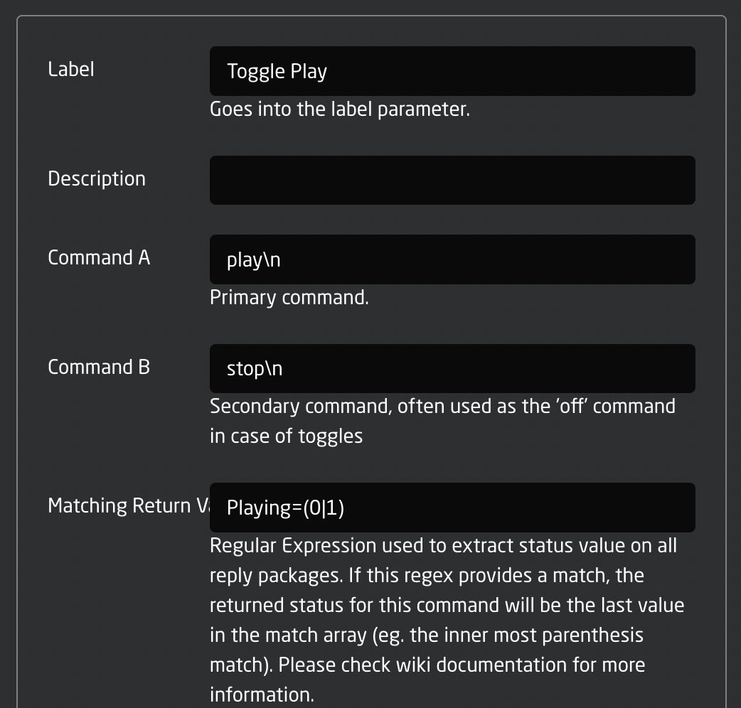
- The Label field will be set as a fixed value in the device core so you can import it as a label in Reactor
- The Command A and B are available to easily create toggle functionality
- The Matching Return Value field contains a regular expression. You can study the format of regular expressions elsewhere, but they are basically very powerful and advanced string matching patterns. Whenever the device core receives feedback from the server it will run all regular expressions set up over each line and whenever there is a match, it will take the value in parenthesis and store as the status value in the corresponding Status parameter in the device core.
The commands configured here will be available through these parameters in the device core:
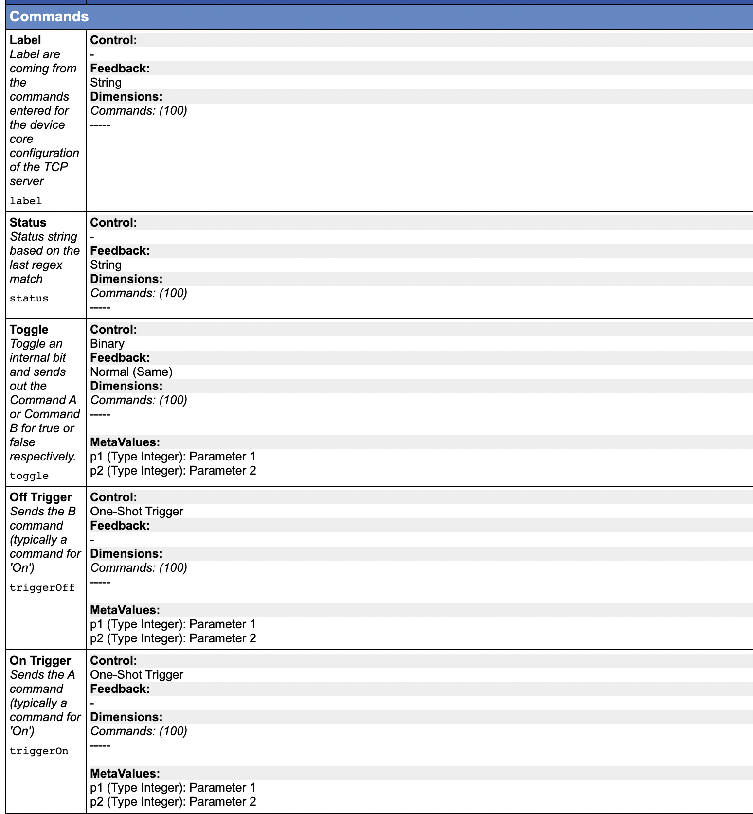
- Toggle, Off Trigger and On Trigger allows various ways of using the command, either by a one-shot type action or by a standard toggle action that keeps internal state in the controller (without any confirmed feedback).
- Label is the text label from configuration. You may want to use this to set a nice title in the displays
- Status is the match value from the last time the regular expression matched the return content. Used carefully, this can provide some feedback from a remote system.
Examples
Forwarding the position of a fader, 0-1000
Forwarding the position value of a fader requires us to use the "\i" placeholder to insert a dynamic value. The code below demonstrates a behavior called "VolumeFader" that is assumed to control volume on a given channel on a device by sending text strings like "CHx_Vol_n", where x is the channel number and n is the volume. In this case, we assume the device will access the value range of n to go from 0 to 1000 so that it's 1:1 compatible with a Raw Panel fader position value.
        "VolumeFader": {
            "ConstantDefinitions": {
                "Channel": {
                    "Description": "Channel",
                    "Type": "Integer"
                },
                "DeviceId": {
                    "Description": "Device Id",
                    "Type": "Integer"
                }
            },
            "EventHandlers": {
                "trigger": {
                    "AcceptTrigger": "Binary",
                    "EventPreProc": {
                        "A2B": {
                            "InputMapping": {
                                "Default": {
                                    "Threshold": 2,
                                    "RepeatThresholds": true,
                                    "OutputTriggerRising": "ActDown",
                                    "OutputTriggerFalling": "ActDown"
                                }
                            }
                        }
                    },
                    "IOReference": {
                        "Raw": "DC:protocol-tcp/{Behavior:Const:DeviceId}/cowboystyle/",
                        "MetaValues": {
                            "command": "CH\\d1_Vol_\\i2",
                            "p1": "Behavior:Const:Channel",
                            "p2": "Behavior:LastEvent/Analog:Value"
                        }
                    }
                }
            }
        }
Description:
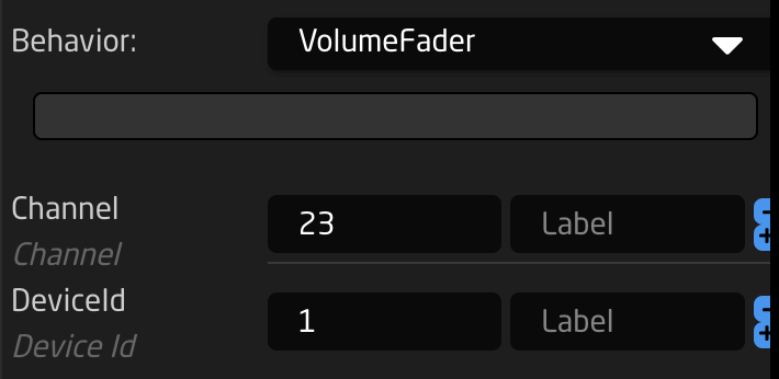
- Lines 2-11 describes a constant definition. This will make the Configuration UI draw up two fields that makes it easy to pick the device ID and Channel number for this behavior. This makes the behavior suitable as a Master Behavior that can be easily reused. It would look like this:

- Lines 14-26: The event handler is set up to trigger on a binary input and the reason why this works for a fader is because the Event Pre Processor in lines 15-26 will convert any change to fader position into a binary trigger.
- Lines 27-24 is the IO reference. When the fader is moved, leading to the generation of a binary trigger, the IO reference is triggered too. The value of the fader is loaded into parameter 2 and the value (constant) of the channel is loaded as parameter 1. Parameter 1 is inserted by \\d1 into the command while the fader value is inserted as \\i2. (The double backslash is the same as a single backslash in JSON)
Forwarding the position of a fader, arbitrary interval
Forwarding the position value of a fader in a different range is more trouble, but can be done. We will use a behavior variable for that. This is a variable only available in the scope of the behavior definition.
        "VolumeFader": {
            "ParentID": "SKAARHOJ:FaderMotorized",
            "Variables": {
                "FaderValue": {
                    "Name": "Volume",
                    "MinMaxCenterValue": [
                        0,
                        100
                    ],
                    "DefaultToFirst": true
                }
            },
            "ConstantDefinitions": {
                "Channel": {
                    "Description": "Channel",
                    "Type": "Integer"
                },
                "DeviceId": {
                    "Description": "Device Id",
                    "Type": "Integer"
                }
            },
            "IOReference": {
                "Raw": "Var:FaderValue"
            },
            "EventHandlers": {
                "forward": {
                    "AcceptTrigger": "Binary",
                    "EventPreProc": {
                        "A2B": {
                            "InputMapping": {
                                "Default": {
                                    "Threshold": 2,
                                    "RepeatThresholds": true,
                                    "OutputTriggerRising": "ActDown",
                                    "OutputTriggerFalling": "ActDown"
                                }
                            }
                        }
                    },
                    "IOReference": {
                        "Raw": "DC:protocol-tcp/{Behavior:Const:DeviceId}/cowboystyle/",
                        "MetaValues": {
                            "command": "CH\\d1_Vol_\\d2",
                            "p1": "Behavior:Const:Channel",
                            "p2": "Var:FaderValue"
                        }
                    }
                }
            }
        },
Description:
- Line 2 defines that we will inherit the master behavior "SKAARHOJ:FaderMotorized". By doing so we "just need" to add an IO reference (parameter) to be changed by the fader and everything else will just work. But, we will extend it quite a bit with some tricks here.
- Lines 3-12 define a behavior variable "FaderValue" which will be used to hold the value we forward. The range is 0-100. This variable can only be used and seen from within this behavior.
- Lines 13-22 has the constants definitions as in the previous example
- Line 24 is the IO reference (parameter) set to the local behavior variable, "FaderValue". So far, what we have is a fader that will simply change the value of the variable "FaderValue" when you move it. Not useful yet.
- Line 27 defines a new event handler which is the code that will take the value of "FaderValue" and forward when the fader is moved. It accepts a binary trigger and has the analog values of the fader generating a binary trigger event when moved (just like in the previous example).
- Lines 44-46 defines the meta values for using the cowboystyle parameter for the TCP device core. Again, the parameters p1 and p2 are loaded with dynamic values from IO references, the Channel constant and the FaderValue respectively. Those are then inserted as decimal bytes in the command string by the placeholders \\d1 and \\d2
Sending TCP commands with an encoder
This examples shows how to program an encoder to send a different command whether you turn it clockwise or counterclockwise. It's build over the same idea as in the previous examples where the behavior is design for use as a Master Behavior, using a constant definition for the channel and Device ID.
        "VolumeUpDown": {
            "Description": "QSYS Volume Up/Down for Encoders/4Ways",
            "ConstantDefinitions": {
                "Channel": {
                    "Description": "Channel",
                    "Type": "Integer"
                },
                "DeviceId": {
                    "Description": "Device Id",
                    "Type": "Integer"
                }
            },
            "IOReference": {},
            "EventHandlers": {
                "down": {
                    "AcceptTrigger": "Binary",
                    "EventPreProc": {
                        "P2B": {
                            "InputPolarity": {
                                "Default": {},
                                "Negative": {
                                    "OutputTrigger": "ActDown",
                                    "OutputEdge": "Left"
                                }
                            },
                            "SpeedmodeConfig": {}
                        }
                    },
                    "BinaryEdgeFilter": "Left",
                    "BinarySetValues": {},
                    "IOReference": {
                        "Raw": "DC:protocol-tcp/{Behavior:Const:DeviceId}/cowboystyle/",
                        "MetaValues": {
                            "command": "CH\\d1_Down",
                            "p1": "Behavior:Const:Channel"
                        }
                    }
                },
                "up": {
                    "AcceptTrigger": "Binary",
                    "EventPreProc": {
                        "P2B": {
                            "InputPolarity": {
                                "Default": {},
                                "Positive": {
                                    "OutputTrigger": "ActDown",
                                    "OutputEdge": "Right"
                                }
                            },
                            "SpeedmodeConfig": {}
                        }
                    },
                    "BinaryEdgeFilter": "Right",
                    "BinarySetValues": {},
                    "IOReference": {
                        "Raw": "DC:protocol-tcp/{Behavior:Const:DeviceId}/cowboystyle/",
                        "MetaValues": {
                            "command": "CH\\d1_Up",
                            "p1": "Behavior:Const:Channel"
                        }
                    }
                }
            },
            "FeedbackDefault": {
                "DisplayText": {
                    "Title": "Ch. {Behavior:Const:Channel} Volume",
                    "Textline1": "Up/Down"
                },
                "Intensity": "Dimmed"
            },
            "FeedbackConditional": {
                "10": {
                    "ActiveIf": "Behavior:Events/trigger:TimeToNow \u003c 300",
                    "Intensity": "On"
                }
            }
        }
Description:
- The event handlers "down" and "up" in lines 15 and line 39 are almost identical and works like this: They activate on a binary trigger, but requires a Left or Right edge press of a four-way button. When encoders sends triggers into this behavior it gets captured and converted by the "P2B" event pre processor that converts a positive encoder pulse into a "right edge" binary trigger. Vice verse for a negative encoder pulse.
- The IO reference in line 55-61 and 31-37 is similar to the ones for faders, but doesn't hold any dynamic value other than the Channel ID from the constants
- In addition, since encoders often has displays, the Feedback Default and Feedback Conditional is set up to show the channel name and blink when activated.