
Core Simulator
The Studio Simulator is a whole TV facility that exists only in software. It pretends to be the routers, vision mixers, cameras, multiviewers, processing boxes and audio consoles of a broadcast plant, and draws the lot as one large picture: where every signal comes from, where it goes, and what is on air. Controllers — flowgrid, Producer Assistant, a panel — talk to it exactly as they would to the real kit, so you can build, demo and test a system with nothing in the rack.
The package is called Studio Sim in skaarOS. Its screen is designed for a 4K display in a booth, but it scales to fit whatever it lands on — a 1080p monitor shows exactly the same picture at half size.
What it does, and what it leaves to the controller
The simulator owns the signal path. For any point in the facility it works out which source actually reaches it, tracing back through router crosspoints, mixer buses, tie-lines and processing loops, and it applies whatever a signal picked up on the way — a colour grade, a keyed logo.
- Routing, cutting and processing — the simulator’s own. Change a crosspoint anywhere and every picture that depends on it follows.
- Camera tally and screen labels (UMD) — the controller’s. The simulator stores what it is told and shows it. With nothing connected, camera tally lamps stay dark, which is the truth rather than a fault.
- Multiviewer tally — the simulator’s, because real multiviewers work that way. Each one is tied to a vision mixer and lights its own tiles from that mixer’s buses, with nobody sending it anything.
Opening it
Install the package, then open Studio Sim from the skaarOS app list. That is the booth screen, and it is the whole user interface — there is nothing else to log into.
Which facility it simulates is called the setup, and four ship with it. You choose one in either of two places:
- the Setup field in the core’s own settings form, or
- the setup parameter on the core’s Setup device (device 1000), which is a drop-down of every setup available — useful from a panel button.
Changing the setup restarts the core. That is deliberate: a facility’s size is fixed when the core starts, so a different one cannot be swapped into a running process. Routing is remembered per setup, so switching away and back returns to what you left.
Two more parameters sit on the Setup device: restart, which restarts on the same setup (the way to pick up a settings change), and resetDemoState, which puts the whole facility back to the show state it boots into.
The four setups
tradeshow — the full facility
The big one, and the default. Two camera studios of four cameras each, two remote sites, four playout servers, two routers joined by tie-lines, two processing boxes and two control rooms. It is the setup to show flowgrid on, because it has the problems flowgrid exists to solve.
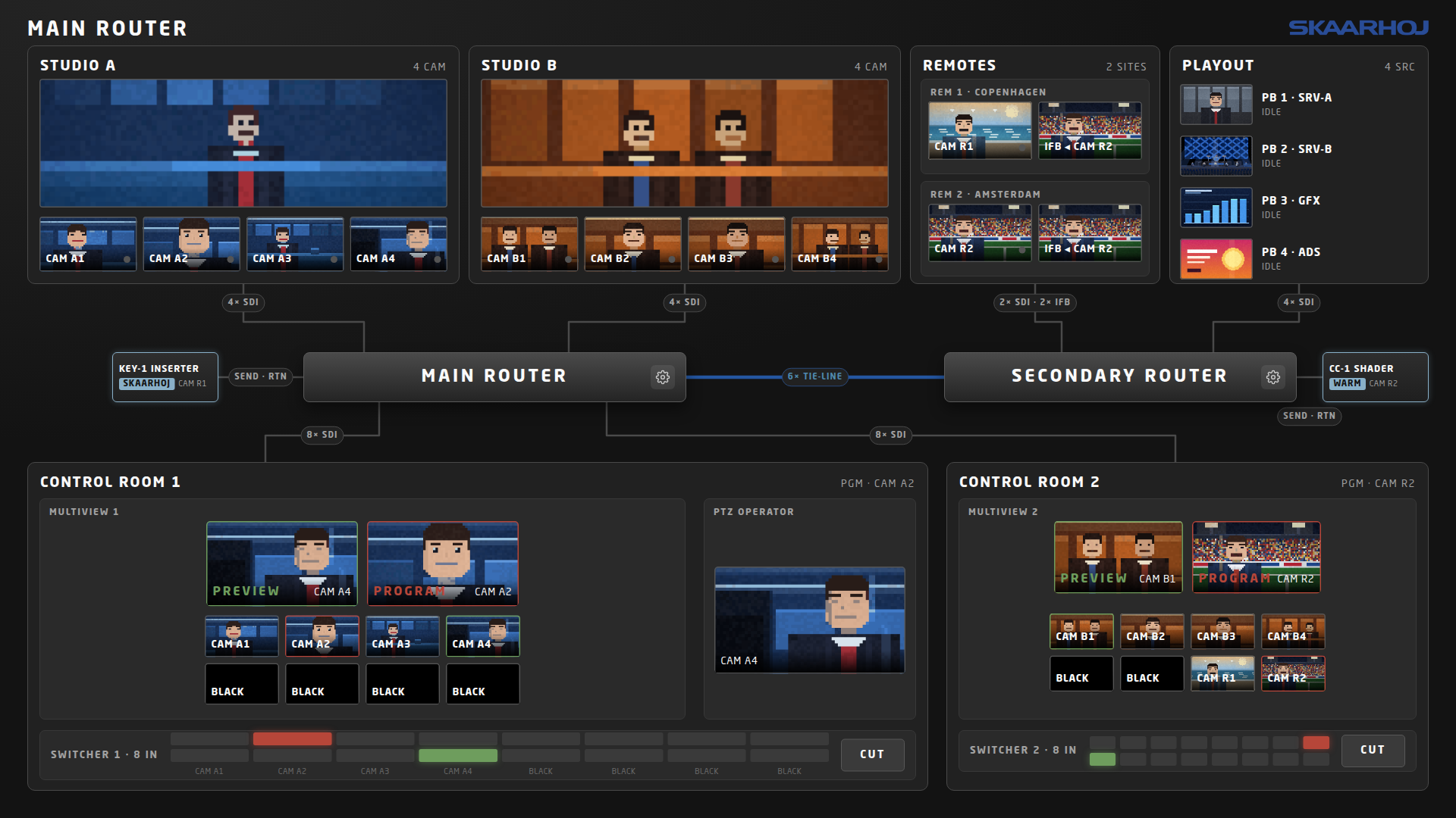
- Only four tie-lines run from the secondary router up to the main one, so the two control rooms can see at most four remote or playout sources between them and have to share. The playout panel says which ones are ‘SHARED · CR1 + CR2’.
- Two processing boxes hang off the routers — a shader (‘CC-1’) and a logo inserter (‘KEY-1’). Each is drawn beside the router it loops through, and says what it is set to do and what is passing through it. A picture that went through one carries a small
CCorKEYbadge. - Eight of the ten cameras are on pan-tilt-zoom heads. Drive one and the picture crops and slides everywhere that camera appears at once. The two remote cameras are somebody else’s kit at the far end of a tie-line, so they carry tally and nothing else.
Nothing in this screen assigns a processing box to a signal — that is flowgrid’s job, and watching flowgrid do it is the point of the demo. At start-up both boxes sit powered up on their working setting with nothing running through them.
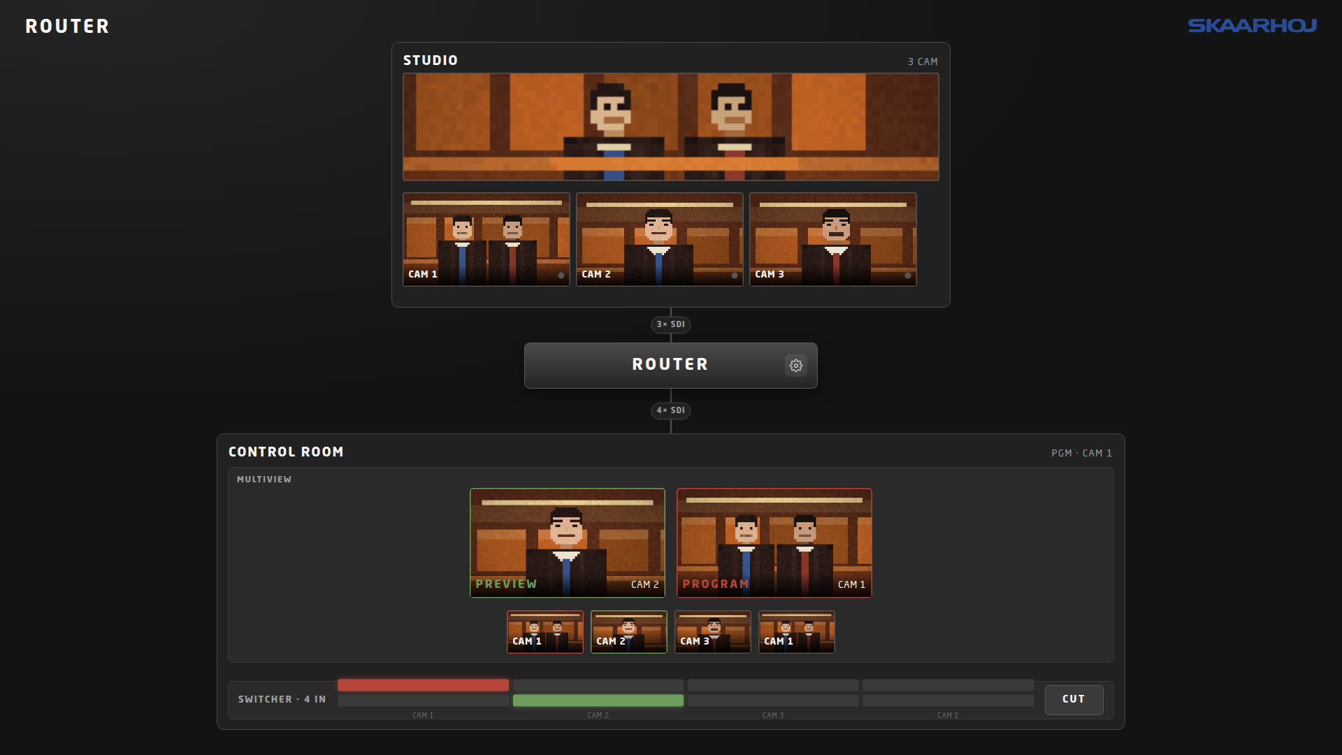
minimal — three cameras and one room
The smallest honest facility: three cameras, one router, one vision mixer, one multiviewer. Use it when the trade-show plant is more than the point you are making, or when you want a screen somebody can take in at a glance.
radio — a visual-radio talk table
Four microphones, an audio console, and four cameras looking at a table of four people. This is the setup for Video Follow Audio: the console meters every channel ten times a second whether or not anything is connected, so a follow-audio controller has a real conversation to react to.
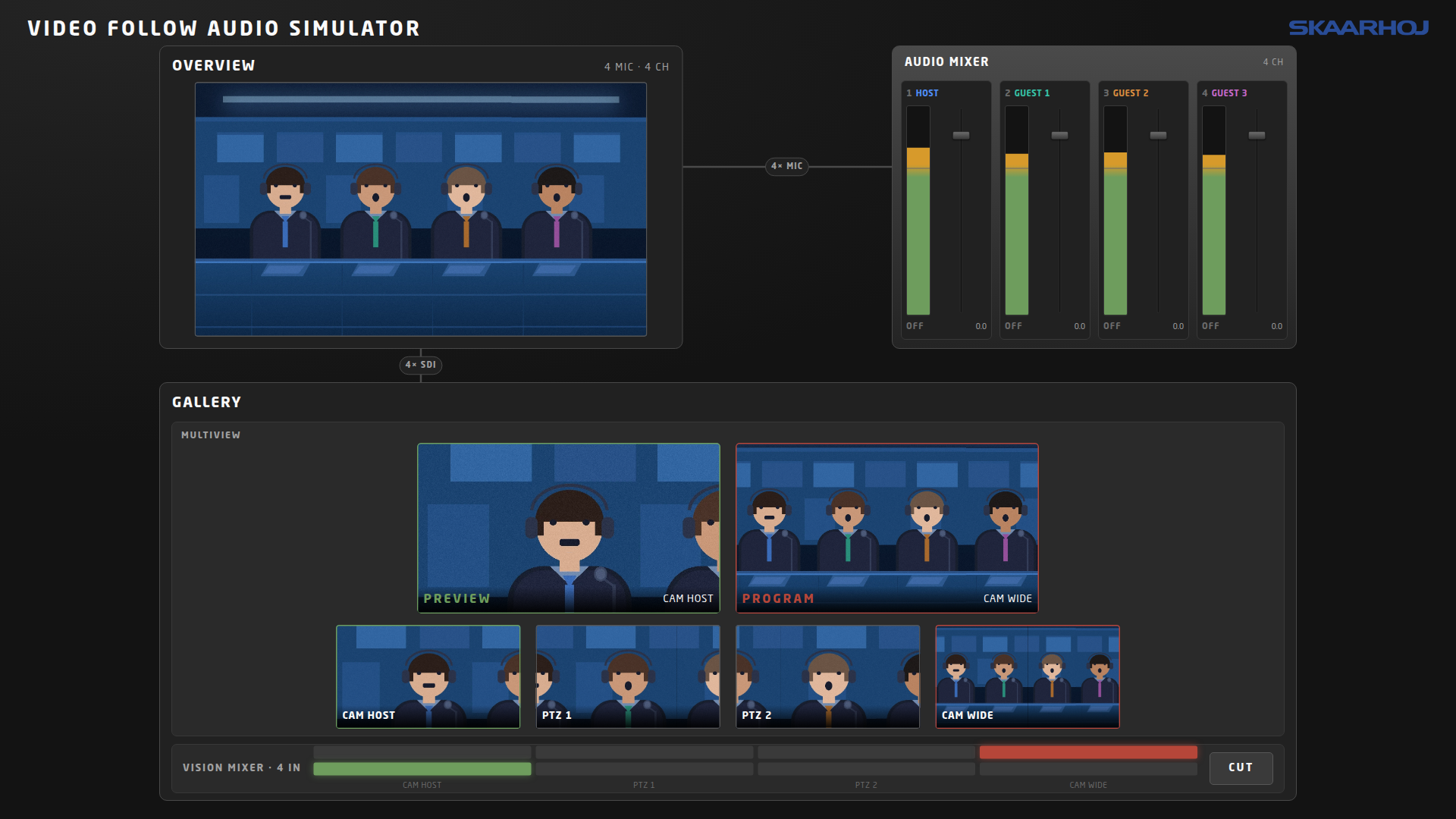
- Channels 1–4 are HOST, GUEST 1, GUEST 2 and GUEST 3 — the console carries microphones and nothing else, so every channel is a person.
- Two heads for four people. Cameras 2 and 3 are on pan-tilt-zoom heads and both know the same eight shots (a single of each seat, three two-shots, and the whole table). Camera 1 is locked on the host and camera 4 is locked wide, and locked really means locked — a stray command cannot drift them off.
- The talk overlaps on purpose. A second voice cuts in near the end of a turn, and now and then everybody speaks at once, so a controller that scores shots rather than single speakers has something to decide.
Camera 4, the locked wide, is the shot to use as a safe source: everyone is in it and it cannot be driven somewhere else while it is on air.
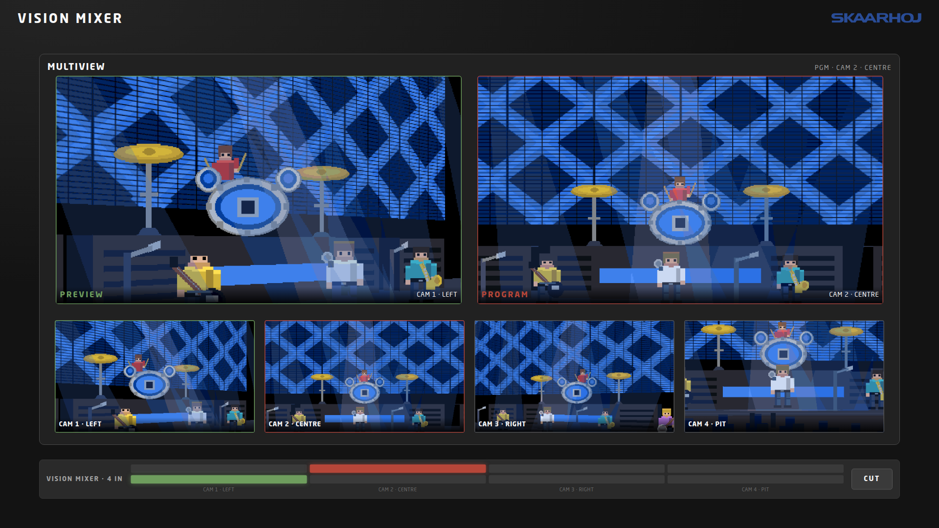
concert — four heads around a stage
A live-music facility: four cameras on heads covering a stage and pit, a vision mixer and a multiview. It exists for Producer Assistant’s PTZ Playlist — the loop where off-air cameras are repositioned, shots are armed on recall and fired on tally. Every camera has a head and opens pushed into the stage, so a move reads as a move.
Reading the screen
- Red is on air, green is preview, and amber means both at once — the same everywhere: camera tiles, multiviewer tiles and the little status dots.
- A tile names what actually reaches it, traced all the way back. A control-room feed arriving over a tie-line names the playout server at the far end, not the tie-line.
- BLACK is a state, not a fault. It shows a flat black slate. ‘NO SIGNAL’ is different: nothing is plugged in or routed there at all.
Driving it by hand
The booth screen is not read-only. Anything you do to it goes down the same path a controller’s commands take, so nothing downstream can tell the difference.
- Program and preview — click any button on a vision mixer’s two rows of buttons.
- Cut — the button at the end of that bar swaps program and preview, exactly as a cut sent from a controller would.
- Reset the show — Shift + R restores the setup’s scripted routing and puts every camera back on the shot it boots with. The
resetDemoStateparameter does the same from a panel button.
The crosspoint sheet
Every router carries a cogwheel. It opens that frame’s crosspoint sheet: one row per output, showing the output’s name, the source currently reaching it, and a cell per input. Click a cell to reroute.
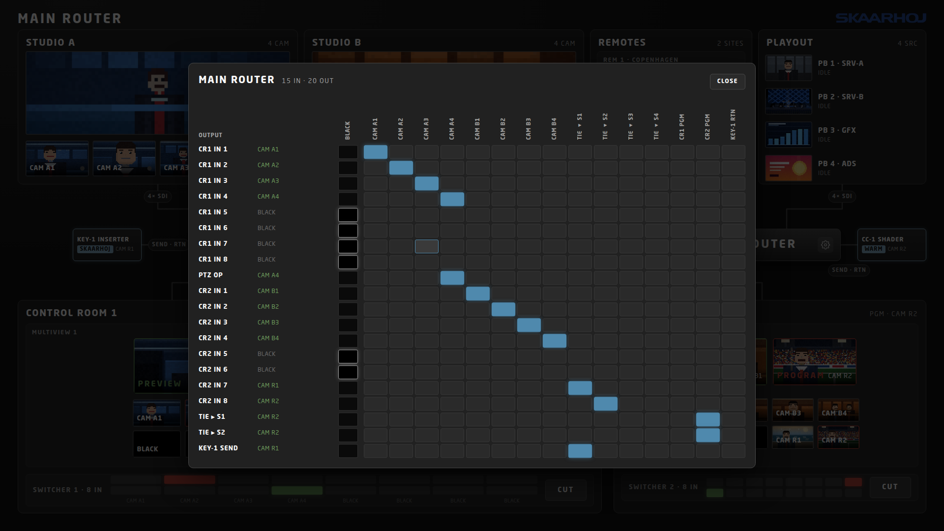
The first column is the black input, set apart from the real ones so it is never picked by accident. Route an output there and it goes black, and the black travels downstream just as a picture would — blank a tie-line and the control-room feeds it carries go black too. Blanking also frees a tie-line rather than making it look busy.
Which sheet is open is remembered by your browser, not by the core. Opening one on a laptop leaves the booth screen alone, and the sheet still updates live while it is open. Esc, Close, or a click outside dismisses it.
The command log
Shift + L cycles a panel off, onto the left, and onto the right. It says in plain English what controllers have told the devices to do — ‘Preview set to CAM A3’, ‘Recalled preset 2’, ‘Started panning right’ — newest at the bottom.
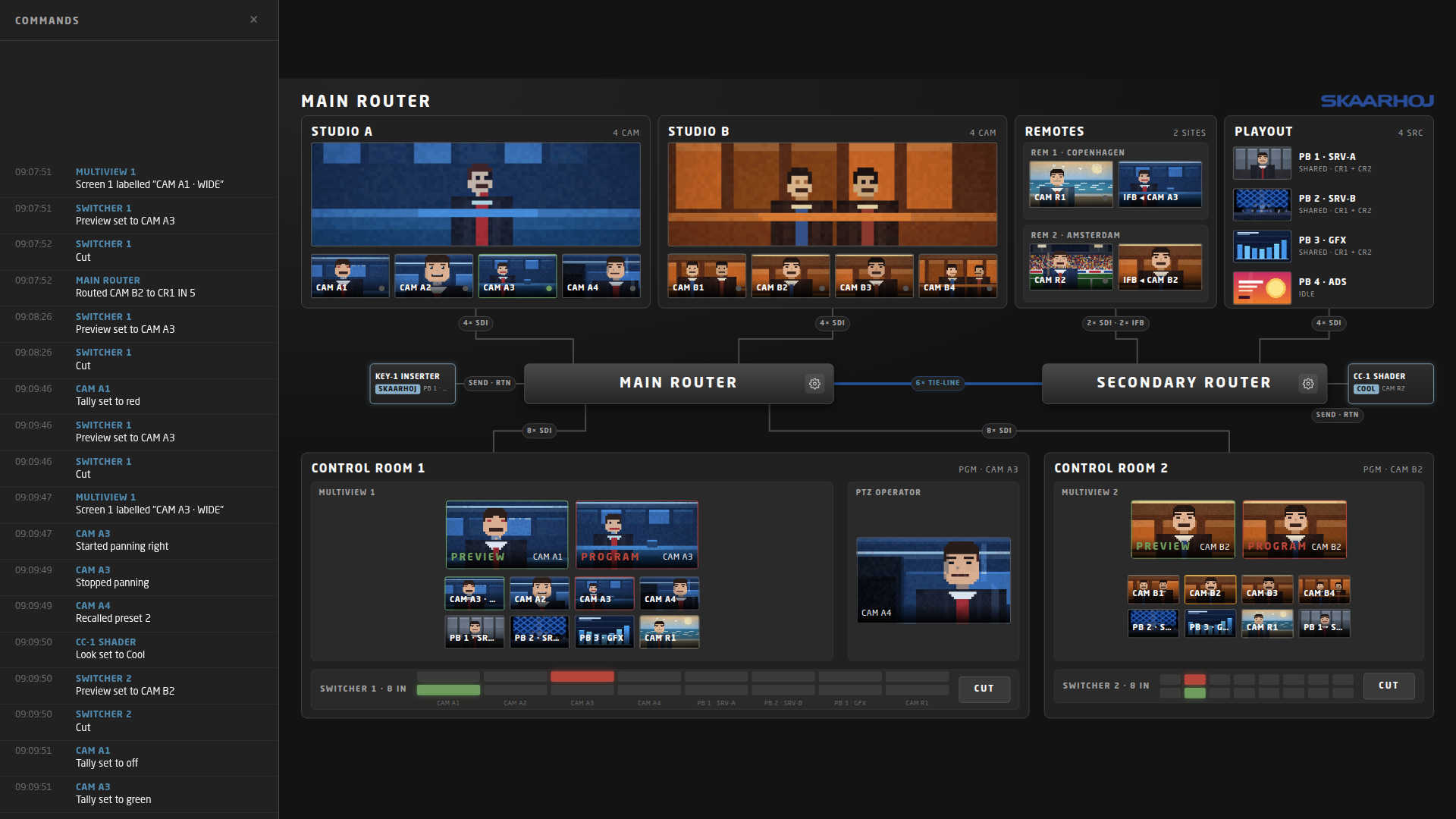
- It logs what arrives from a controller, and only that. A command sent to a device that is switched off still gets a line, because the controller did send it. Clicking around this screen produces no lines at all — somebody at the booth screen is not a controller.
- Joysticks and faders are collapsed to one gesture. A stick writes a line when it leaves centre and another when it returns; a fader writes one line when the move settles.
- Nothing is saved. It holds the last 200 lines in memory and is gone on restart — it is a demo aid, not a record.
This is the panel to point at when somebody asks why their button did nothing. It answers “what did the controller actually send”, which is usually the question.
Connecting a controller
From Producer Assistant
Add a module device and point its Endpoint at the machine the simulator runs on. On skaarOS, leave it empty — the core is found by name. Discovery then lists the simulated devices, and you address parameters the usual way, typing the parameter name in:
- Program and preview —
programInput,previewInput - Transition —
cut - Camera framing —
panSpeed,tiltSpeed,zoomSpeed,presetRecall - Router crosspoints —
routeInputToOutput - Audio meters —
audioLevel, addressed per channel
This core is not in Producer Assistant’s parameter table, so nothing is filled in for you and the names above have to be typed exactly. They read a little differently from some cores — presetRecall, not ‘recallPreset’ — because the same names are the contract the generated flowgrid topology is built from.
From flowgrid
The trade-show setup ships with a matching flowgrid topology file — every crosspoint, tie-line, camera tally reference and label destination, generated from the facility definition so the two cannot drift apart. Import it into flowgrid and point flowgrid at this core.
Flowgrid project can be downloaded here.
The control-room outputs deliberately declare no tally destination. The simulator owns multiviewer tally, and pointing flowgrid at it as well would have the two writing over each other. Camera tally is still flowgrid’s and is declared on the inputs.
The pictures in the tiles
Every 16:9 tile is filled from a small animated picture named after its source — cam-a1.gif, studio-a.gif, pb-3.gif. A source with no file shows a generated stand-in tinted with the source’s colour, so a facility is never empty. You can add or replace pictures from the setup editor; see the companion article below.
One source is one picture and therefore one file, which is why a camera’s studio tile and its multiviewer tile play in step rather than drifting apart.
Building your own facility
The four setups above are built into the core, but you are not limited to them. The simulator has a browser editor for building a facility of your own — devices, cabling, sources and the drawing itself — with no code involved. Press Shift + E on the booth screen to open it. See Building Your Own Studio Setup.
Troubleshooting
- Camera tally lamps are all dark — expected with no controller connected. Camera tally belongs to the controller; the simulator only shows what it is told. Multiviewer tiles light on their own.
- A tile says NO SIGNAL — nothing is routed to that point, or nothing is cabled into it. Open the router’s crosspoint sheet and look at the row.
- A tile is black — something is routed there: the black input, either directly or somewhere upstream. Black travels down the chain.
- A control room cannot see a remote or playout source — in the trade-show setup, that is the tie-line limit doing its job. Only four sources can cross at once.
- A tile shows a striped stand-in — there is no picture file for that source key. Upload one in the setup editor, named after the key.
- The core will not settle on a setup — if the configured setup no longer exists, the core says so in its log and steps down to a setup that does rather than refusing to start.
Reference
- Setup device — device 1000:
setup(choose the facility, restarts),restart,resetDemoState. Device ids at or above 1000 are reserved for it. - Keyboard — Shift + R reset the show state, Shift + L cycle the command log left / right / off, Shift + E open the setup editor, Esc close an open crosspoint sheet.
- What survives a restart — router and mixer routing, saved per setup. Tally, labels and audio meters do not, because restoring a stale copy would show a lie until a controller reconnected.
- The device list in the settings form is generated from the setup on every start. Editing it does nothing; change the setup instead.
- Screen size — the picture is laid out at 3840 × 2160 and scaled to fit, so the composition never reflows.