Mapping
The Mapping section is built into the Panels section and is designed to provide a view into the current configuration and often it will refer to embedded standard configuration with associated constant sets for setting up cameras, router input/outputs or switcher inputs.
Configuration
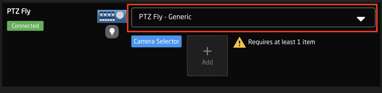
The drop down allows you select from the default configurations Skaarhoj has made for the specific panel type and from your user generated configurations, create custom configurations, or remove configurations. Most often the needed default camera control configuration will be the Generic Control configuration. This one is designed to be the most flexible for adding multiple brands of cameras with extreme ease.
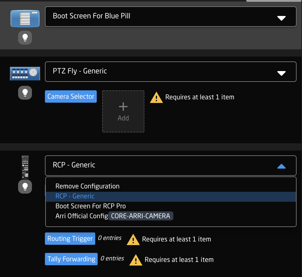
User generated or modified configurations will displays with an orange CUSTOMIZED label next to it. 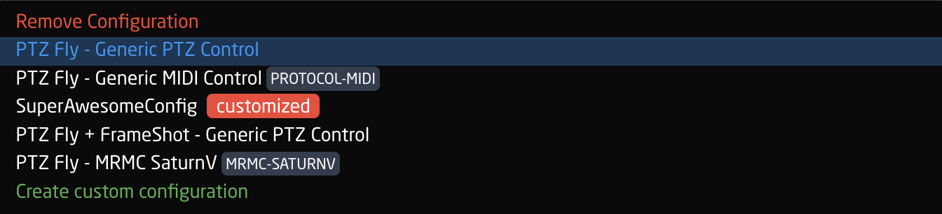
Constant Sets
The final step is to fill in any setup tables, also known as constant sets. The constant sets are available based on the chosen configuration and should contain entries such as specific cameras for a PTZ controller, or the inputs for a video switcher etc. They are most common when working with PTZ cameras and routing panels, though may be available for additional device configurations. A detailed breakdown of using available constant sets tables can be found on our wiki page: https://wiki.skaarhoj.com/books/blue-pill-reactor/chapter/understanding-constant-sets
The setup tables will auto save and quickly appear on displays and enable the function.
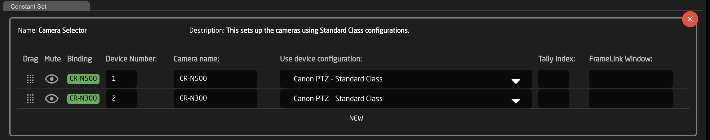
An example of a setup table would be a camera selector and can be seen below. These can be different depending on the selected configuration. From here the order on the camera selector row of the panel will be set as well as the desired name on the displays.
There are a couple of ways to work with the camera selector.
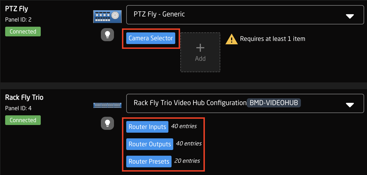
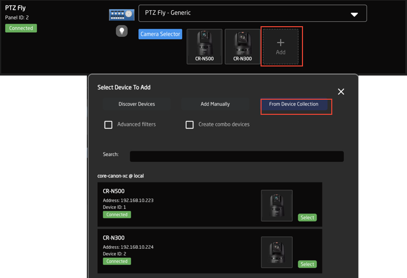
In the Panels Section, it is possible to click the ADD button next to the Camera Selector to select a device already in the device collection in the devices section or to add a new discovered or manually added device. Adding one with Discovered or Manually will require additional information added in the Devices section. Using a device from the current Device Collection will auto populate the Camera Selector, though it is still smart to click into the selector to double check the information is correct.
It is possible in the click and drag the camera icons in the Panels section to rearrange the camera selector row on your panel. The order that is seen in the home screen will be the order on the panel.
Clicking on the Camera Selector button will open the camera selector’s Constant Set box. In there are a variety of options, some of which are not available in the Panels section. These options are device and configuration specific so may vary.
|
Column |
Description |
|
Drag |
Allows for quick rearranging of camera order. Right clicking on drag will allow for deleting the row. |
|
Mute |
Allows for removing access to a specific camera or to leave a blank spot on the panel |
|
Binding |
Allows for the selecting of a specific connected camera |
|
Camera Name |
Customizable name to appear on the displays. Character limit is determined by size of display and can vary. |
|
Device Number |
Ties the camera selector to the specific device. This is found in the Devices section. Each device will have a unique device number per device core. This box should auto-populate when a camera is selected in binding |
|
Link Selector |
Selects the protocol based configuration associated with camera. Needed protocol can be seen in the Devices section, each device is grouped into their native protocols. Double check the correct configuration is selected. Improper selection will effect camera control. |
|
Channel Link |
Selects the needed protocol for Iris/Master Black control. For cameras without a variable lens this will follow the same protocol as the device. For cameras with a variable lens, select the protocol for the attached lens. Not available on all configuration classes. |
|
Tally Index |
Sets the Tally Index number to connect with associated tally source device. See Blue Pill/Reactor Manual for more information. This column does not need to be filled out for standard operation. |
|
Route Index |
Sets the Route Index number to connect with associated routing device. See Blue Pill/Reactor Manual for more information. This column does not need to be filled out for standard operation. |
|
FrameLink Window |
Sets the FrameLink Window value associated with the FrameLink device core for use with FrameLink compatible devices. See Blue Pill/Reactor Manual for more information. This column does not need to be filled out for standard operation. |
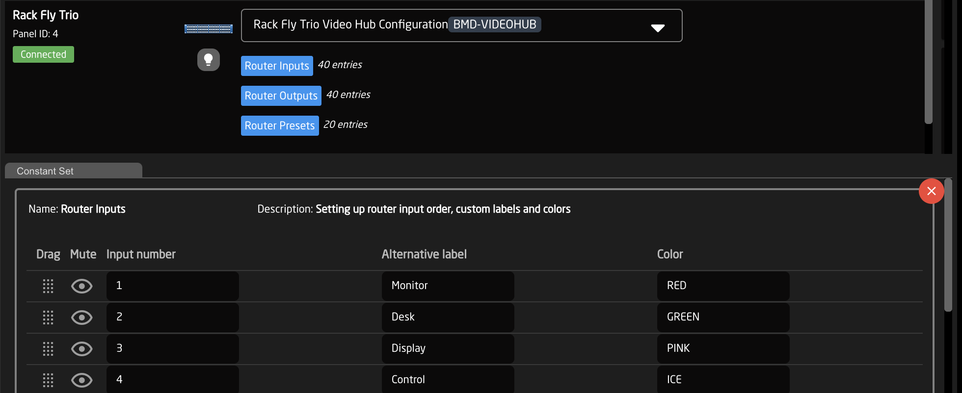
An example of a router inputs selector can be seen below. These can be different depending on the selected configuration and device. From here the order on the inputs/outputs row of the panel will be set as well as the desired name on the displays and button color.
|
Column |
Description |
|
Drag |
Allows for quick rearranging of input/output order on the panel. |
|
Mute |
Allows for removing access to a specific input/output or to leave a blank spot on the panel. |
|
Output Number/Input Number |
Ties the selector to the specific input/output of the controlled device. This is determined by the individual router. |
|
Alternative Label |
Customizable name to appear on the displays. Character limit is determined by size of display and can vary. |
|
Color |
Sets the button feedback color. Color options are: OFF, WHITE, WARM, RED, ROSE, PINK, PURPLE, AMBER, YELLOW, DARKBLUE, BLUE, ICE, CYAN, SPRING, GREEN, MINT. |